Khi người dùng lắp đặt các đồng hồ lưu lượng vào hệ thống ống, họ thường gặp phải các câu hỏi về phương pháp lắp đặt, mối quan hệ giữa đường kính trong và ngoài, và cách chọn kích thước phụ kiện phù hợp. LORRIC tận dụng kinh nghiệm thực tế rộng rãi và kiến thức ngành để chi tiết hóa sự tương ứng của kích thước phụ kiện với đường kính trong và ngoài của ống. Bài viết này giới thiệu các tiêu chuẩn sản xuất, vật liệu thông dụng và phương pháp lắp đặt, giúp người dùng chọn lựa kích thước phụ kiện phù hợp qua bài viết này.
1. Các Phụ Kiện PPH, PVDF Tuân Thủ Tiêu Chuẩn ISO
LORRIC sản xuất các phụ kiện hàn nhiệt PPH và PVDF dựa trên tiêu chuẩn ISO:
( 1 ) Vật liệu PPH (ISO 15494) Phụ kiện hàn Butt và Socketweld
ISO 15494 chỉ định các tính chất và điều kiện của các thành phần làm từ một số vật liệu nhất định (như ống, phụ kiện và van) chủ yếu được sử dụng trong các hệ thống ống nhựa nhiệt dẻo trong các ứng dụng công nghiệp dưới mặt đất và trên mặt đất: polybutylene (PB), polyethylene (PE), polyethylene nhiệt độ cao (PE-RT), polyethylene liên kết chéo (PE-X), polypropylene (PP).
*Tiêu chuẩn này định nghĩa nhiều vật liệu, nhưng nội dung liên quan đến ISO 15494 được cung cấp trong bài viết này chỉ áp dụng cho polypropylene (PP).
( 2 ) Vật liệu PVDF (ISO 10931) Phụ kiện hàn Butt và Socketweld
ISO 10931 chỉ định các hệ thống ống nhựa cho các ứng dụng công nghiệp (các thành phần và hệ thống làm từ polyvinylidene fluoride (PVDF)).
2. Chỉ Số Áp Suất và Độ Bền - Tỷ Lệ Tiêu Chuẩn Kích Thước SDR và Dòng Ống S
SDR (Tỷ Lệ Kích Thước Tiêu Chuẩn) và S (Dòng Ống) chủ yếu mô tả mối quan hệ giữa kích thước ống và độ dày thành ống. Giá trị SDR càng cao, thành ống càng mỏng; giá trị thấp hơn, thành ống càng dày, đóng vai trò là chỉ số về khả năng chịu áp suất và độ bền cấu trúc.
Lưu ý: Do các sức mạnh cơ học khác nhau của vật liệu, SDR chỉ có thể so sánh trong cùng một vật liệu, không thể so sánh giữa các vật liệu khác nhau.
3. Thông Số Kỹ Thuật Ống PPH, PVDF
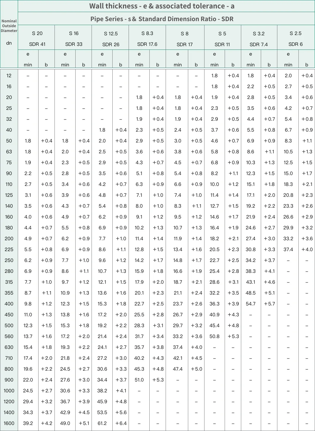
( 1 ) Thông Số Kích Thước Ống PPH (mm)

a: Tất cả kích thước tuân thủ ISO 4065.
b: Công thức tính dung sai là (0.1e + 0.2) mm, làm tròn đến 0.1 mm gần nhất.
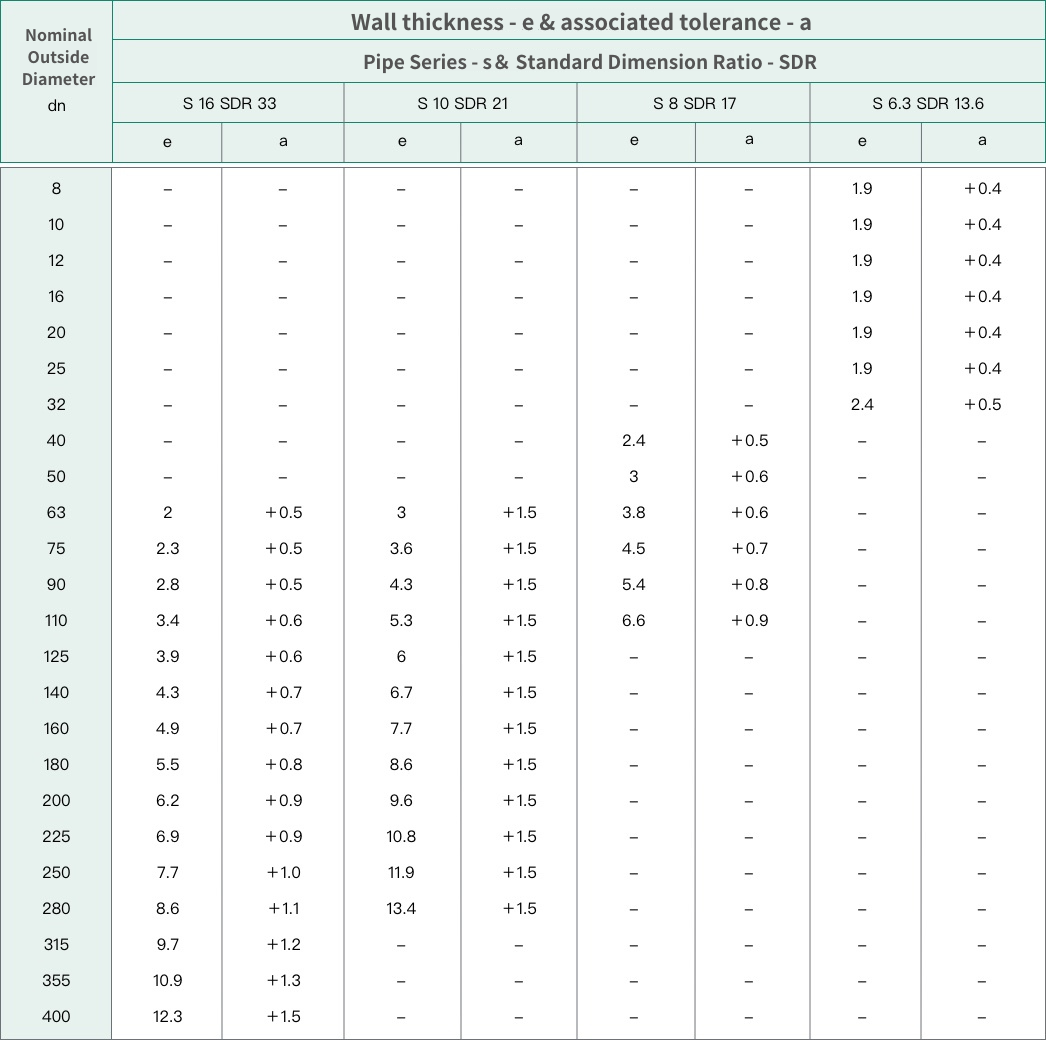
( 2 ) Thông Số Kích Thước Ống PVDF (mm)

*Vì lý do an toàn, độ dày thành ống tối thiểu không được nhỏ hơn 1.9 mm.
Dung sai độ dày thành ống: (0.1 e + 0.2) mm, làm tròn đến 0.1 mm gần nhất.
Tất cả kích thước dựa trên ISO 4065.
4. Các Phương Pháp Lắp Đặt Ống Thường Dùng Cho Phụ Kiện PPH, PVDF
( 1 ) Hàn Butt
Quy trình ống: Các mặt giao diện của hai ống cần kết nối được làm nóng và chảy đến một mức độ nhất định. Sau khi kết nối hai mặt giao diện đã được làm nóng và cho phép chúng nguội và đông đặc, quy trình hàn được hoàn tất. Vì không cần tiêu thụ một đoạn ống để làm nóng và lắp vào, phương pháp này tiết kiệm vật liệu hơn, và mối nối ít bị rò rỉ và chịu được áp suất cao hơn.
a ) Kích Thước Đầu Hàn Butt Phụ Kiện PVDF
e: Độ dày thành của đầu spigot của phụ kiện, nằm trên Lb1, phải tuân theo các thông số kỹ thuật ống PVDF như đã liệt kê trong mục ba (3.1).
Lb1: Chiều dài hình trụ nội bộ tối thiểu của đầu hàn nóng chảy, tức là độ sâu ban đầu của đầu spigot yêu cầu cho hàn butt.
Lb2: Chiều dài hình trụ ngoài tối thiểu của đầu hàn nóng chảy, tức là chiều dài ban đầu của đầu hàn nóng chảy.
| dn |
Lb1 |
Lb2 |
| 8 |
4
|
10 |
| 10 |
4 |
10 |
| 16 |
4 |
10 |
| 20 |
4 |
10 |
| 25 |
4
|
10 |
| 32 |
5 |
10 |
| 40 |
5 |
10 |
| 50 |
5 |
12 |
| 63 |
6 |
12 |
| 75 |
6 |
12 |
| 90 |
7 |
12 |
| 110 |
8 |
12 |
| 125 |
8 |
15 |
| 140 |
9 |
15 |
| 160 |
9 |
20 |
| 180 |
10 |
20 |
| 200 |
11 |
20 |
| 225 |
12 |
25 |
| 250 |
13 |
25 |
| 280 |
14 |
30 |
| 315 |
15 |
30 |
*The cylindrical length may be reduced for fittings that are allowed to be bent.
a ) Kích Thước Đầu Hàn Butt Phụ Kiện PPH
e: Độ dày thành của đầu spigot để lắp vào, nằm trên Lb1, phải tuân theo bảng kích thước ống PPH (tham khảo mục ba, mục 1).
Lb1: Chiều dài nội bộ của đầu spigot để lắp vào.
Lb2: Chiều dài bên ngoài của đầu spigot để lắp vào.
| dn |
Lb1 |
Lb2 |
| 12 |
4
|
10 |
| 16 |
4 |
10 |
| 20 |
4 |
10 |
| 25 |
4 |
10 |
| 32 |
5
|
10 |
| 40 |
5 |
10 |
| 50 |
5 |
12 |
| 63 |
6 |
12 |
| 75 |
6 |
12 |
| 90 |
7 |
12 |
| 110 |
8 |
12 |
| 125 |
8 |
15 |
| 140 |
9 |
15 |
| 160 |
9 |
20 |
| 180 |
10 |
20 |
| 200 |
11 |
20 |
| 225 |
12 |
25 |
| 250 |
13 |
25 |
| 280 |
14 |
30 |
| 315 |
15 |
30 |
| 355 |
16 |
30 |
| 400 |
18 |
30 |
| 450 |
20 |
35 |
| 500 |
20 |
35 |
| 560 |
20 |
40 |
| 630 |
20 |
40 |
| 710 |
20 |
40 |
| 800 |
20 |
50 |
| 900 |
20 |
50 |
| 1000 |
20 |
60 |
| 1200 |
20 |
60 |
| 1400 |
20 |
70 |
| 1600 |
20 |
70 |
*Các đầu nối có thể uốn cong có thể có chiều dài phần hình trụ giảm ở đầu cắm của ống.
( 2 ) Hàn Đầu Ống Socket
Quá trình hàn đầu ống socket liên quan đến việc làm nóng bề mặt ngoài của một ống và bề mặt trong của một ống khác. Khi vẫn còn nóng, ống đã nóng chảy sẽ được chèn vào ống kia và giữ nguyên vị trí cho đến khi mối nối nguội đi. Đường kính ngoài của ống chèn phải khớp với đường kính trong của ống socket để, sau khi chảy và nguội, chúng tạo thành một liên kết chắc chắn. Việc chú ý đến đường kính trong và ngoài của các ống, cũng như độ dày thành ống là rất quan trọng; hơn nữa, vì ống được chèn vào, chiều dài mở rộng của ống chèn cũng phải được tính đến. Ví dụ, đối với ống có đường kính Ø20, chiều dài mở rộng phải lớn hơn 10mm; bộ gia nhiệt phải vừa vặn với ống để làm nóng nó đúng cách trong thời gian quy định nhằm đạt được sự chảy nhựa.
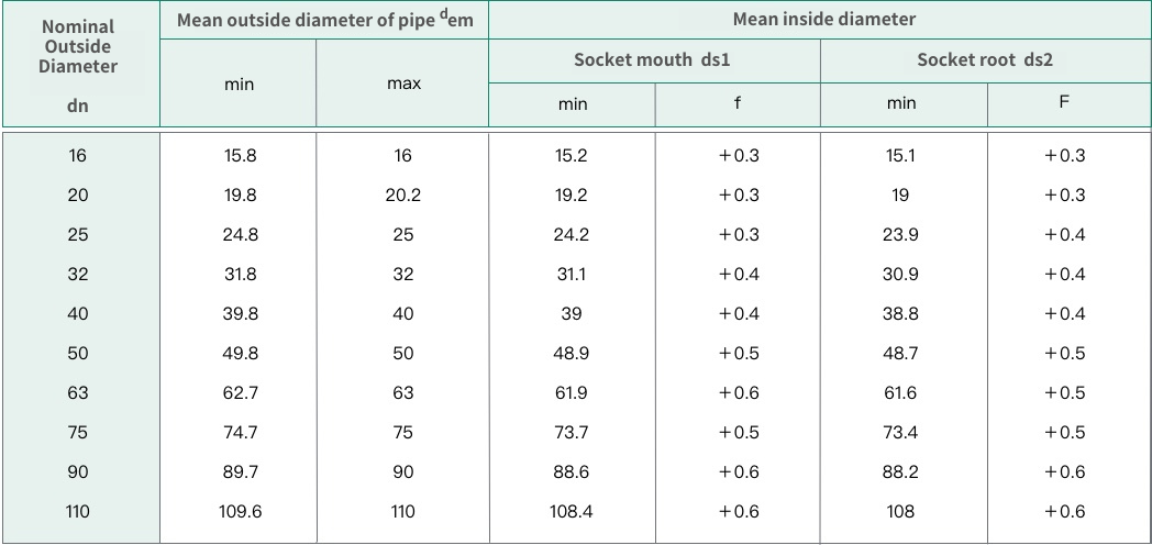
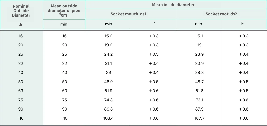
dn: Đường kính danh nghĩa
ds1: Đường kính trong của đầu socket, bao gồm đường kính trung bình của vòng tròn trong phần mở rộng có mặt đầu socket.
ds2: Đường kính trong trung bình ở đáy của socket, bao gồm đường kính trung bình của vòng tròn trong mặt phẳng song song với mặt đầu socket, ở khoảng cách Ls, là chiều dài socket tham chiếu.
ds3: Đường kính của kênh dòng chảy (lỗ) xuyên qua thân ống.
Ls: Chiều dài socket tham chiếu, bao gồm cả chiều dài tối thiểu lý thuyết. Đây là chiều dài được sử dụng để tính toán.
Ls1: Chiều dài socket thực tế, bao gồm khoảng cách từ đầu socket đến vai.
Ls2: Chiều dài đầu hàn đã được nung nóng, bao gồm chiều dài xâm nhập của công cụ gia nhiệt vào socket.
Ls3: Chiều dài chèn, bao gồm chiều sâu xâm nhập từ đầu ống đã được gia nhiệt vào socket.
Ls4: Chiều dài gia nhiệt ống, bao gồm chiều sâu của ống khi chèn vào công cụ gia nhiệt.
a ) Kích Thước Đầu Hàn Socket PVDF và Chiều Dài (ISO 10931)

b ) Kích Thước Đầu Hàn Socket PPH và Chiều Dài (ISO 15494)
