เครื่องวัดการไหลแบบใบพัด (Paddle Wheel Flow Meter)
เครื่องวัดการไหลแบบใบพัดใช้การหมุนของใบพัดตามอัตราการไหลของของเหลว เหมาะสำหรับของเหลวหนืดต่ำ เช่น น้ำ น้ำมัน และสารเคมี มีความแม่นยำปานกลาง ตอบสนองไว ติดตั้งและดูแลง่าย แต่ต้องทำความสะอาดและตรวจสอบเป็นประจำเพื่อรักษาประสิทธิภาพ.
การตรวจจับอัจฉริยะแบบเรียลไทม์ (Real-Time Smart Detection)
ระบบตรวจจับอัจฉริยะสามารถ แจ้งเตือนความผิดปกติของใบพัดได้อย่างชัดเจน ซึ่งเป็น สิ่งจำเป็นสำหรับการผสานระบบกับ Industry 4.0 ช่วยแก้ไขปัญหาการไหลได้อย่างรวดเร็วโดย ซิงค์ข้อมูลกับระบบจัดการโรงงาน
ด้วย เซ็นเซอร์แม่เหล็กในตัว (Built-in Magnetic Sensing) ระบบสามารถตรวจสอบ ความแรงของแม่เหล็กในใบพัด เพื่อให้มั่นใจใน ความแม่นยำของการวัดการไหลที่สม่ำเสมอ ผ่านการ ตรวจสอบเป็นประจำและการเปลี่ยนชิ้นส่วนตามกำหนดเวลา
ข้อต่อท่อเกรดพรีเมียม: ทนทานและไร้ปัญหารั่วซึม
สัมผัสความทนทานสูงสุดกับข้อต่อท่อของ LORRIC ผลิตจากแท่งรีดเพื่อขนาดคงที่และผิวในเรียบ ลดการรบกวน เพิ่มความแม่นยำ แข็งแรงกว่าข้อต่อฉีดขึ้นรูป ปราศจากปัญหาแฟลช รอยเชื่อม และการขึ้นรูปไม่สมบูรณ์ มั่นใจในคุณภาพที่คุณคู่ควร!
วิธีฉีดพลาสติกแบบดั้งเดิมทำให้ข้อต่อสามทางมีผิวไม่เรียบและเกิดลอน เนื่องจากพลาสติกหลอมถูกบีบอัด ทำให้ส่วนหนาหดตัวมากขึ้น ส่งผลให้พื้นที่หน้าตัดไม่สม่ำเสมอ การไหลของของไหลไม่เสถียร และคำนวณค่าได้ไม่แม่นยำ นอกจากนี้ ข้อต่อฉีดขึ้นรูปยังมีปัญหาแฟลช การขึ้นรูปไม่สมบูรณ์ และรอยเชื่อมอ่อน ทำให้เสี่ยงต่อการเสียหายมากขึ้น ในทางกลับกัน ข้อต่อสามทางของ LORRIC ผลิตด้วยเทคนิคขั้นสูง ให้ผิวเรียบและทนทาน แก้ปัญหาของวิธีเดิมได้อย่างมีประสิทธิภาพ.
สามารถเปลี่ยนทิศทางของหน้าจอได้ตามท่อแนวตั้งหรือแนวนอน
ปรับทิศทางการมองเห็นของหน้าจอให้ตรงตามทิศทางของท่อ ซึ่งสะดวกสำหรับการตรวจสอบการไหลในสถานการณ์การท่อที่แตกต่างกัน
เรียนรู้เพิ่มเติม: วิธีการติดตั้งเครื่องวัดการไหลแบบใบพัด
เทคโนโลยี Pulse 2.0
เครื่องวัดการไหลแบบใบพัดที่มี สัญญาณพัลส์แบบดั้งเดิม ใช้ ค่า K คงที่ ตลอดช่วงการวัด ซึ่งนำไปสู่ ความคลาดเคลื่อนที่สูงขึ้น โดยเฉพาะเมื่อ อัตราการไหลเปลี่ยนแปลง ยกตัวอย่างเช่น เครื่องวัดการไหลแบบใบพัดใน ท่อ DN15 จะ ส่งสัญญาณทุก 90 องศา โดยมีค่า 106.55 พัลส์เท่ากับ 1 ลิตร โดยไม่คำนึงถึงความเร็วของการไหล
เทคโนโลยี Pulse 2.0 ที่เป็นเอกสิทธิ์ของ LORRIC ซึ่งขับเคลื่อนด้วย AxleSense Technology สามารถ ส่งพัลส์ 1 ครั้งต่อทุกๆ 0.01 ลิตร โดยปรับค่าตาม ความเร็วการไหลที่แตกต่างกัน เพื่อลดข้อผิดพลาดและเพิ่มความแม่นยำในการวัด
|
FP-P015 |
FP-P020 |
FP-P025 |
FP-P032 |
FP-P040 |
FP-P050 |
FP-P065 |
Installation method
|
in-line
|
Applicable pipe
diameter |
d 20 (mm)
DN 15
(mm)
DN 1/2
(inch) |
d 25 (mm)
DN 20
(mm)
DN 3/4
(inch) |
d 32 (mm)
DN 25
(mm)
DN 1
(inch) |
d 40 (mm)
DN 32
(mm)
DN 1-1/4
(inch) |
d 50 (mm)
DN 40
(mm)
DN 1-1/2
(inch) |
d 63 (mm)
DN 50
(mm)
DN 2
(inch) |
d 76 (mm)
DN 65
(mm)
DN 2-1/2
(inch) |
T-connector material
|
UPVC / PPH / PVDF (Made to order)/ 316L Stainless Steel |
Paddle material
|
PVDF or PPH with embedded magnet + ceramic bearing and shaft |
Applicable fluid
|
Various fluid with less impurities (<1%)
|
Applicable fluid maximum
dynamic viscosity
|
300cSt ** |
| Fluid in pipes temperature |
UPVC :0~45°C (32~122°F)
PPH: 0-80
PVDF:0-100
ss316L:0-100 ** |
Device working environment temperature
|
-10~60°C (14~140°F)
|
| Velocity range |
± 0.3~10m/s Can extend to ± 0.15m ~ 10m/s
(Please note that the minimum flow value may vary slightly due to flow field factors specific to individual models.) |
| Flow range |
3.6-120.6
LPM |
5.7-188.5
LPM |
8.8-294.5
LPM |
13.6-452.9
LPM |
22.6-754.0
LPM |
36.8-1225.7
LPM |
65.4-2179.0
LPM |
0.95-28.4
gpm |
1.5-49.86
gpm |
2.32-80.81
gpm |
3.59-139.86
gpm |
5.97-190.36
gpm |
9.72-313.77
gpm |
17.27-526.29
gpm |
| Language |
English, Chinese
|
| Unit |
Metric: Liter, cubic meters, meters
Time: second, minute, hour, day
Imperial: foot, Cubic foot, Uk gallon, US gallon |
| Display |
16x3 3-Color Backlight 10-bit LCD display |
| Display update cycle |
1s
|
| Measurement accuracy |
±2.5% OR***
|
| Linearity |
± 0.5 % FS (>0.3m/s) |
Power supply
|
DC 24V 100mA(not included in the communication current) |
Power I/O Connector
|
6-pin connector
|
| Input/Output |
FP-AS310A (A version): Analog output with self-powered 10-bit 4-20mA / NPN
FP-AS310R (R version): Modbus RTU RS485
|
Protection circuit
|
Power reverse connection protection, Power surge protection |
Waterproof level
|
IP66 **** |
| Transient data |
Instantaneous flow rate
|
| Cumulative data |
Positive flow |
| Operation button |
4 Key touch buttons |
| Cable length |
2 meters long |
* The device is calibrated with water at normal temperature before leaving the factory. Using fluids with viscosities different from water may result in inaccurate calibration values and could affect the minimum and maximum flow rates.
** The working temperature range for each material is provided as a reference. Please use your design experience to make the final material selection.
*** The measurement accuracy is determined through laboratory testing with clean water at a controlled room temperature of 25 degrees Celsius. Actual usage conditions may introduce errors.
**** IP66 stands for 'Ingress Protection,' which signifies the degree of protection an electrical device's enclosure offers against foreign object intrusion. The IP rating format consists of two digits, expressed as IPXX. The first digit denotes the level of protection against solid objects, particularly dust resistance, while the second digit indicates the waterproof protection level. A higher number signifies better protection. In the case of IP66, the first '6' indicates full dust protection, while the second '6' means no harm from high-pressure water splashes.
| FP-P015 |
| Size |
Connector |
Spec |
Material |
| 1/2" |
Male Thread
|
BSPT |
UPVC / PVDF |
| NPT |
UPVC / PVDF |
Female Thread
|
BSPT |
UPVC / PVDF |
| NPT |
UPVC / PVDF |
| Socket
|
CNS |
UPVC |
| JIS |
UPVC |
| ANS |
UPVC
|
| DIN |
UPVC
|
| Butt Fusion |
ISO |
PPH / PVDF |
| Socket Fusion |
ISO |
PPH / PVDF |
| FP-P020 |
| Size |
Connector |
Spec |
Material |
| 3/4" |
| Male Thread
|
BSPT |
UPVC / PVDF |
| NPT |
UPVC / PVDF |
| Female Thread
|
BSPT |
UPVC / PVDF |
| NPT |
UPVC / PVDF |
Socket
|
CNS |
UPVC |
| JIS |
UPVC |
| ANS |
UPVC
|
| DIN |
UPVC
|
| Butt Fusion |
ISO |
PPH / PVDF |
| Socket Fusion |
ISO |
PPH / PVDF |
| FP-P025 |
| Size |
Connector |
Spec |
Material |
| 1" |
| Male Thread
|
BSPT |
UPVC / PVDF |
| NPT |
UPVC / PVDF |
| Female Thread
|
BSPT |
UPVC / PVDF |
| NPT |
UPVC / PVDF |
| Socket
|
CNS |
UPVC |
| JIS |
UPVC |
| ANS |
UPVC
|
| DIN |
UPVC
|
| Butt Fusion |
ISO |
PPH / PVDF |
| Socket Fusion |
ISO |
PPH / PVDF |
| FP-PO32 |
| Size |
Connector |
Spec |
Material |
| 1-1/4" |
| Male Thread
|
BSPT |
UPVC / PVDF |
| NPT |
UPVC / PVDF |
| Female Thread
|
BSPT |
UPVC / PVDF |
| NPT |
UPVC / PVDF |
| Socket
|
CNS |
UPVC |
| JIS |
UPVC |
| ANS |
UPVC
|
| DIN |
UPVC
|
| Butt Fusion |
ISO |
PPH / PVDF |
| Socket Fusion |
ISO |
PPH / PVDF |
| FP-P040 |
| Size |
Connector |
Spec |
Material |
| 1-1/2" |
| Male Thread
|
BSPT |
UPVC / PVDF |
| NPT |
UPVC / PVDF |
| Female Thread
|
BSPT |
UPVC / PVDF |
| NPT |
UPVC / PVDF |
| Socket
|
CNS |
UPVC |
| JIS |
UPVC |
| ANS |
UPVC
|
| DIN |
UPVC
|
| Butt Fusion |
ISO |
PPH / PVDF |
| Socket Fusion |
ISO |
PPH / PVDF |
| FP-P050 |
| Size |
Connector |
Spec |
Material |
| 2" |
| Male Thread
|
BSPT |
UPVC / PVDF |
| NPT |
UPVC / PVDF |
| Female Thread
|
BSPT |
UPVC / PVDF |
| NPT |
UPVC / PVDF |
| Socket
|
CNS |
UPVC |
| JIS |
UPVC |
| ANS |
UPVC
|
| DIN |
UPVC
|
| Butt Fusion |
ISO |
PPH / PVDF |
| Socket Fusion |
ISO |
PPH / PVDF |
| flange |
JIS 10K
|
UPVC
|
| FP-P065 |
| Size |
Connector |
Spec |
Material |
| 2-1/2" |
| Butt Fusion |
ISO |
PPH / PVDF |
| Socket Fusion |
ISO |
PPH / PVDF |
| Socket |
CNS |
UPVC |
| JIS |
UPVC |
| ANS |
UPVC
|
| DIN |
UPVC
|
| flange |
JIS 10K |
UPVC |
⚠Safety instructions:
1. After the warranty, the electronic components of the product will age due to time and operating environment. Under long-term use, please replace the new product according to the condition of the product.
2. Do not operate the product under an Orange or Red LCD Backlight for a long time. Product damage and related losses may occur.
Conditions and Disclaimer:
CONDITIONS: Equipment sold by LORRIC is not intended to be used, nor shall it be used:
(1) As a "Basic Component" under 10 CFR 21 (NRC), used in or with any nuclear installation or activity; or (2) In medical applications or used on humans. Should any product(s) be used in or with any nuclear installation or activity, medical application, used on humans, or misused in any way, LORRIC assumes no responsibility as set forth in our basic WARRANTY/ DISCLAIMER language, and, additionally, purchaser will indemnify LORRIC and hold LORRIC harmless from any liability or damage whatsoever arising out of the use of the product(s) in such a manner.
DISCLAIMER: Please be aware that magnetic fields or residual magnetism may cause interference to the flowmeter which may result in damage if they are used near the installation site. The purchaser must determine the applicability of the product for its desired use and assumes all risks in connection therewith. LORRIC assumes no responsibility or liability for any omissions or errors in connection with the use of its products.
The alarm used to detect paddle damage or loss is intended to assist on-site operators to find out what is causing equipment abnormalities. Because there are a myriad of variables involved with on-site operation and magnetic fields that come from other equipment, the alarm function is liable to fail. Please do not take the alarm function as a single source for monitoring your flow system. Please contact LORRIC for advanced help.
กรุณาสั่งซื้อตามข้อมูลด้านล่าง
-
เลือกตัวเครื่องวัดอัตราการไหลและขั้วต่อสายเคเบิล (ตัวอย่างรหัสสั่งซื้อ: FP-AS310A(R))
-
เลือกข้อต่อรูปตัว T + ชุดใบพัดตามขนาด, วัสดุ, ประเภท และข้อกำหนดของท่อ (ตัวอย่าง: FP-P050CUAV)
- หากต้องการสั่งซื้อทั้งชุด ให้รวมรหัสทั้งสองเข้าด้วยกัน
- ตัวอย่าง: FP-AS310A(R) + FP-P050CUAV
(ดาวน์โหลดแคตตาล็อกดูรายละเอียด)
Size
| UPVC pipe - union diameter size(mm) |
|
A |
B
|
C
|
D
|
E
|
F
|
G
|
H
|
| ½" |
164 |
100 |
27.6 |
36 |
62.3 |
46.2 |
115.7 |
86.2 |
¾"
|
168 |
100 |
32.6 |
41.9 |
62.3 |
50.5 |
115.7 |
&85.7 |
1"
|
168 |
100 |
40.6 |
50 |
62.3 |
60 |
115.7 |
85.7 |
1¼"
|
210 |
114 |
50.2 |
59.6 |
65 |
75.6 |
127 |
89.2 |
1½"
|
218 |
120 |
56 |
65.7 |
70 |
83 |
134 |
92.5 |
2"
|
269.5 |
133.3 |
72 |
81 |
81 |
99.7 |
148.8 |
99 |
| UPVC pipe - spigot pipe diameter size(mm) |
|
A |
B
|
C
|
D
|
E
|
F
|
| 2½" |
160 |
70 |
76 |
92 |
106.5 |
152.5 |
| Device size(mm) |
| I |
J |
| 63 |
63 |
| Connector (mm) |
| K |
L |
| 47.8 |
30.0 |
Applications

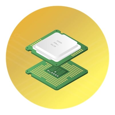
แผงวงจรพิมพ์ (PCB)
เครื่องวัดการไหลในกระบวนการชุบไฟฟ้าและการกัด PCB ใช้ตรวจสอบการไหลของสารเคมีและของเหลวทำความสะอาด หัวฉีดควบคุมการเคลือบและการล้างสารเคมี

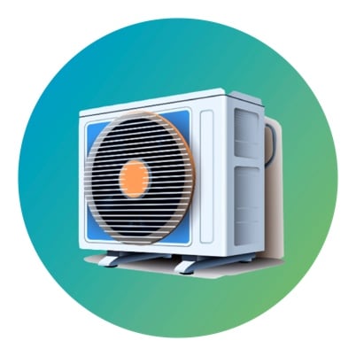
ระบบปรับอากาศ
เครื่องวัดการไหลช่วยตรวจสอบและควบคุมการไหลของน้ำเย็นและน้ำร้อน โดยติดตามการใช้พลังงานของเครื่องทำความเย็น หัวฉีดช่วยปรับสมดุลการไหลของน้ำในระบบเหล่านี้เพื่อเพิ่มประสิทธิภาพ

น้ำบริสุทธิ์
เครื่องวัดการไหลตรวจสอบการใช้น้ำเพื่อควบคุมประสิทธิภาพ ส่วนหัวฉีดเพิ่มประสิทธิภาพการพ่นเพื่อลดต้นทุนบำบัดน้ำ

การบำบัดน้ำเสีย
เครื่องวัดการไหลช่วยตรวจสอบน้ำเข้า-ออก เพิ่มประสิทธิภาพและความแม่นยำในการบำบัดน้ำเสีย ขณะที่หัวฉีดพ่นสารเคมีในกระบวนการ เพื่อให้สอดคล้องกับมาตรฐานสิ่งแวดล้อม