1. Góc phun" là gì?
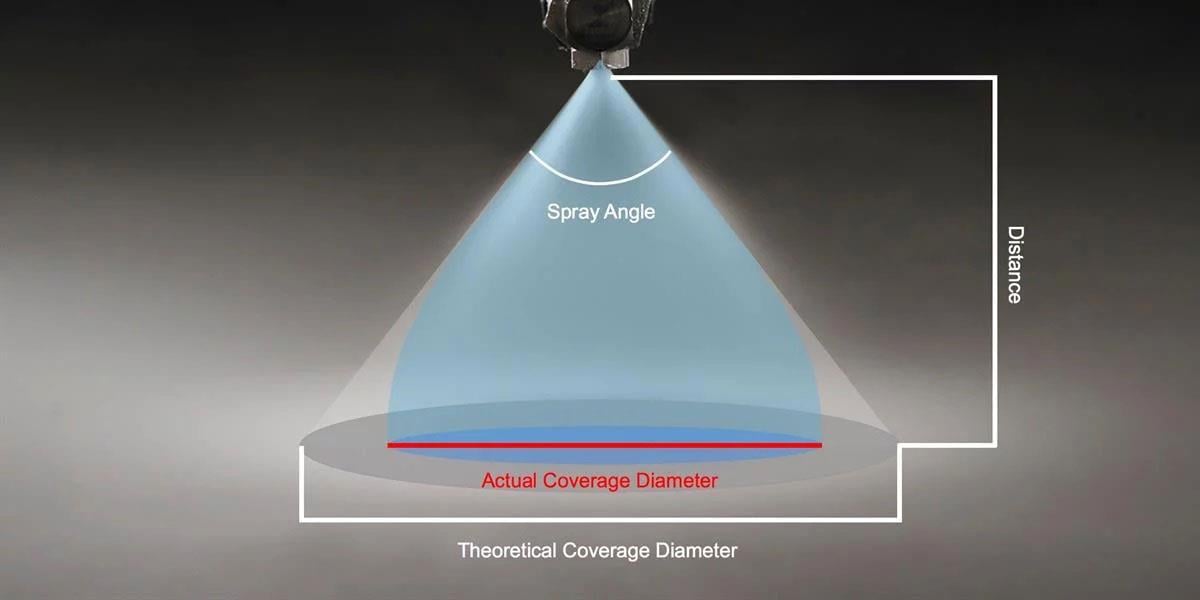
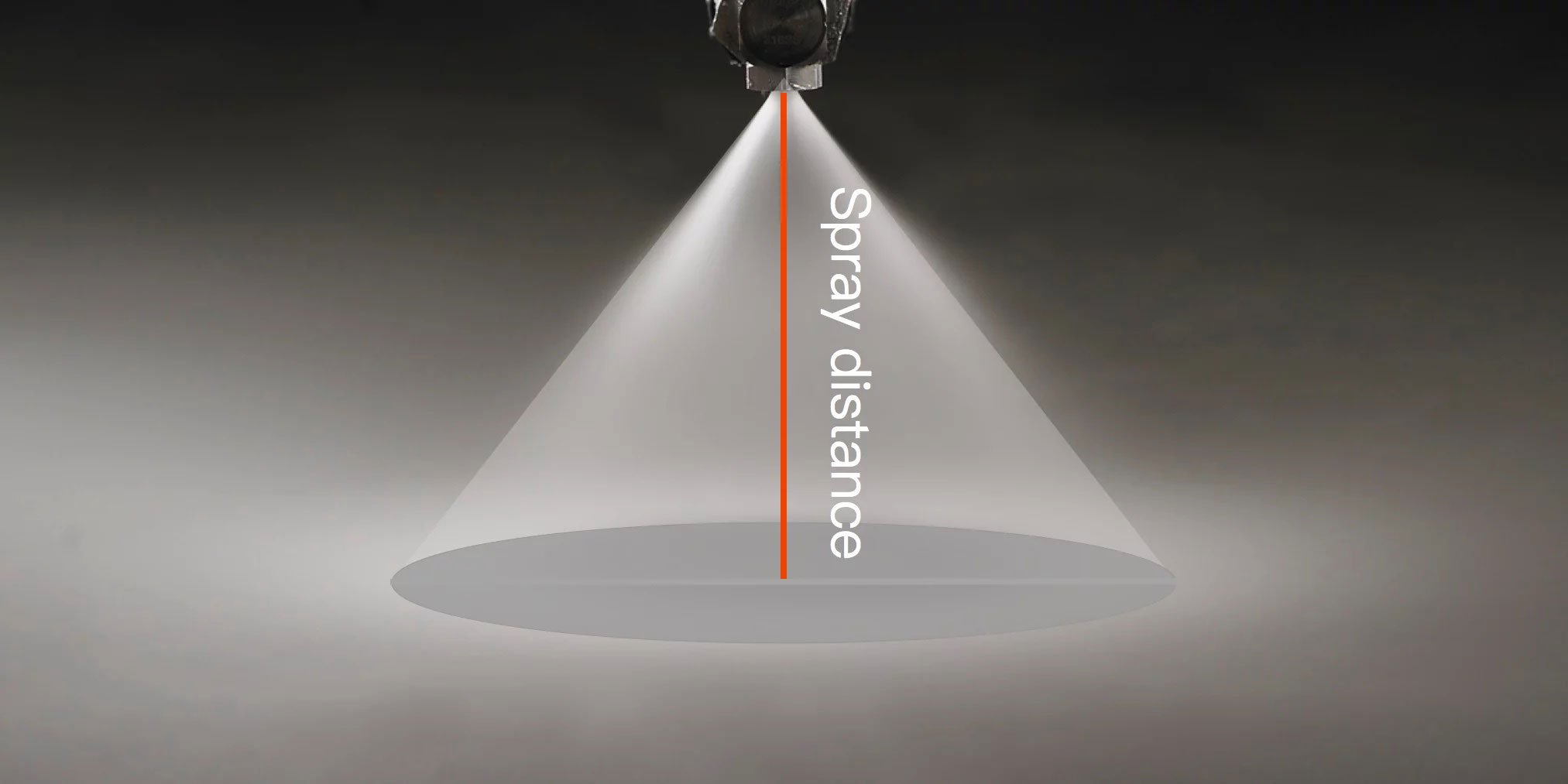
Khi chúng ta đề cập đến góc phun (góc nón phun), chúng ta đang nói đến góc được hình thành giữa đường tâm của lỗ thoát đầu phun và các cạnh của tia phun ở cả hai bên. Sau khi chất lỏng thoát ra khỏi đầu phun, nó không thể tiếp tục theo hướng tiếp tuyến do tác động của gia tốc trọng lực và sức cản không khí. Do đó, "khu vực bao phủ phun thực tế" có thể nhỏ hơn so với "khu vực bao phủ phun lý thuyết".
2. Làm thế nào để tính toán góc phun?
Hiện nay, không có phương pháp đo góc phun được tiêu chuẩn hóa quốc tế, nhưng các kỹ thuật đo phổ biến bao gồm phương pháp sử dụng thước đo góc và phương pháp đo quang học.
- Phương pháp đo góc bằng thước đo góc truyền thống:
Vòi phun được cố định và giữ ở vị trí nằm ngang. Một thước đo góc được sử dụng để căn chỉnh với các cạnh của tia phun phát ra từ tâm vòi phun, và góc phun được đọc. Phương pháp này có chi phí thấp nhưng có thể bị ảnh hưởng bởi sai sót do con người.
- Phương pháp đo quang học:
Sử dụng một nguồn sáng ổn định, một máy ảnh độ phân giải cao sẽ ghi lại hình dạng của tia phun. Phần mềm máy tính chuyên dụng, như CAD hoặc phần mềm xử lý hình ảnh, sau đó được sử dụng để tính toán góc phun. Phương pháp này có độ chính xác cao nhưng yêu cầu phần mềm đắt tiền và chuyên môn chuyên sâu. LORRIC sử dụng phương pháp đo quang học để đảm bảo chất lượng của mỗi vòi phun trước khi xuất xưởng.
3. Làm thế nào để tính toán góc phun?
Khu vực bao phủ phun lý thuyết của đầu phun bị ảnh hưởng bởi cả kích thước lỗ phun của đầu phun và khoảng cách giữa đầu phun và bề mặt mục tiêu. Mối quan hệ này cũng xác định khu vực bao phủ phun và mật độ chất lỏng tương ứng với khu vực được bao phủ.
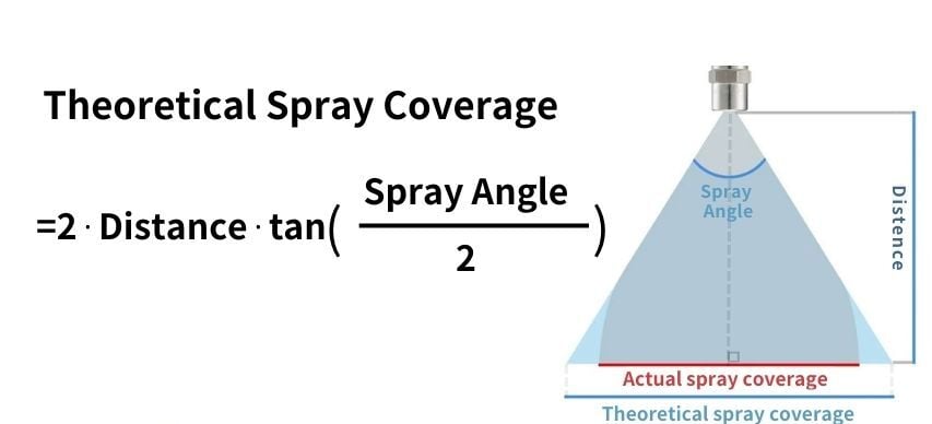
Để tính toán diện tích bao phủ của tia phun lý thuyết, chúng ta cần biết cả góc phun và khoảng cách giữa miệng vòi phun và vật thể. Công thức tính diện tích bao phủ của tia phun là như sau:
Diện tích bao phủ tia phun lý thuyết = 2⋅Khoảng cách⋅tan(Góc phun/2)

Tóm lại, mối quan hệ giữa góc phun, khu vực bao phủ và khoảng cách là: nói chung, góc phun càng lớn thì khu vực bao phủ càng rộng, nhưng khoảng cách phun sẽ ngắn hơn. Ngược lại, góc phun nhỏ hơn sẽ tạo ra khu vực bao phủ hẹp hơn nhưng cho phép tia phun đạt được khoảng cách xa hơn.
4. Bảng tham khảo Góc phun và Khu vực bao phủ
LORRIC cung cấp một bảng tham khảo hiển thị các góc phun đã được tính toán và các khu vực bao phủ tương ứng dựa trên công thức. Cần lưu ý rằng, do các yếu tố như trọng lực và sự lệch hướng khí động học, góc phun chỉ có thể duy trì trong một khoảng cách giới hạn—thường là tối đa 300 mm từ lỗ thoát đầu phun.
Đơn vị: inch
Góc phun
(°)
|
Khu vực bao phủ phun lý thuyết (Đơn vị: inch) |
| 40 |
55 |
60 |
65 |
70 |
75 |
80 |
90 |
100 |
120 |
170 |
|
Khoảng cách
(đơn vị: inch)
|
1.0
|
0.7 |
1.0 |
1.2 |
1.3 |
1.4 |
1.5 |
1.7 |
2.0 |
2.4 |
3.5 |
23 |
|
1.5
|
1.1 |
1.6 |
1.7 |
1.9 |
2.1 |
2.3 |
2.5 |
3.0 |
3.6 |
5.2 |
34 |
|
2.0
|
1.5 |
2.1 |
2.3 |
2.5 |
2.5 |
2.8 |
4.2 |
4.0 |
6.0 |
8.7 |
57 |
|
2.5
|
1.8 |
2.6 |
2.9 |
3.2 |
3.5 |
3.8 |
5.0 |
5.0 |
7.2 |
10 |
69 |
|
3.0
|
2.2 |
3.1 |
3.5 |
3.8 |
4.2 |
4.6 |
5.0 |
6.0 |
7.2 |
10 |
69 |
|
3.5
|
2.5 |
3.6 |
4.0 |
4.5 |
4.9 |
5.4 |
5.9 |
7.0 |
8.3 |
12 |
80 |
|
4.0
|
2.9 |
4.2 |
4.6 |
5.1 |
5.6 |
6 |
6.7 |
8.0 |
10 |
14 |
91 |
|
4.5
|
3.3 |
4.7 |
5.2 |
5.7 |
6.3 |
7 |
7.6 |
9.0 |
11 |
16 |
103 |
|
5
|
3.6 |
5.2 |
5.8 |
6.4 |
7 |
8 |
8.4 |
10 |
12 |
17 |
114 |
|
6
|
4.4 |
6.2 |
6.9 |
7.6 |
8 |
9 |
10 |
12 |
14 |
21 |
137 |
|
7
|
5.1 |
7.3 |
8.1 |
8.9 |
10 |
11 |
12 |
14 |
17 |
24 |
160 |
|
8
|
5.8 |
8.3 |
9 |
10 |
11 |
12 |
13 |
16 |
19 |
28 |
183 |
|
9
|
6.6 |
9.4 |
10 |
11 |
13 |
14 |
15 |
18 |
21 |
31 |
206 |
|
10
|
7.3 |
10.4 |
12 |
13 |
14 |
15 |
17 |
20 |
24 |
35 |
229 |
|
11
|
8.0 |
11.5 |
13 |
14 |
15 |
17 |
18 |
22 |
26 |
38 |
251 |
|
12
|
8.7 |
12.5 |
14 |
15 |
17 |
18 |
20 |
24 |
29 |
42 |
274 |
|
13
|
9.5 |
12 |
15 |
18 |
20 |
22 |
23 |
26 |
31 |
45 |
297 |
|
14
|
10 |
13 |
16 |
17.8 |
19.7 |
21.8 |
24 |
28 |
33 |
48 |
320 |
|
18
|
13 |
19 |
21 |
23 |
25 |
28 |
30 |
32 |
43 |
62 |
411 |
|
20
|
15 |
21 |
23 |
25 |
28 |
31 |
34 |
36 |
48 |
69 |
457 |
|
22
|
16 |
23 |
25 |
28 |
31 |
34 |
37 |
40 |
52 |
76 |
503 |
|
24
|
17 |
25 |
28 |
31 |
34 |
37 |
40 |
44 |
57 |
83 |
549 |
|
26
|
19 |
27 |
30 |
33 |
36 |
40 |
44 |
48 |
62 |
90 |
594 |
|
28
|
20 |
29 |
32 |
36 |
39 |
43 |
47 |
52 |
67 |
97 |
640 |
|
30
|
22 |
31 |
35 |
38 |
42 |
46 |
50 |
56 |
72 |
104 |
686 |
|
32
|
23 |
33 |
37 |
41 |
45 |
49 |
54 |
60 |
76 |
111 |
732 |
|
34
|
25 |
35 |
39 |
43 |
48 |
52 |
57 |
64 |
81 |
118 |
777 |
|
36
|
26 |
37 |
42 |
46 |
50 |
55 |
60 |
60 |
86 |
125 |
823 |
Đơn vị: mm
Góc phun (°) |
Khu vực bao phủ phun lý thuyết (Đơn vị: mm) |
| 55 |
60 |
65 |
70 |
80 |
75 |
90 |
100 |
120 |
|
Khoảng cách
(đơn vị: mm)
|
30 |
31 |
35 |
38 |
42 |
50 |
46 |
60 |
72 |
104 |
| 40 |
42 |
46 |
51 |
56 |
67 |
61 |
80 |
95 |
139 |
| 50 |
52 |
58 |
64 |
70 |
84 |
77 |
100 |
119 |
173 |
| 60 |
62 |
69 |
76 |
84 |
101 |
92 |
120 |
143 |
208 |
| 70 |
73 |
81 |
89 |
98 |
117 |
107 |
140 |
167 |
242 |
| 80 |
83 |
92 |
102 |
112 |
160 |
123 |
160 |
191 |
277 |
| 90 |
94 |
104 |
115 |
126 |
180 |
138 |
180 |
215 |
312 |
| 100 |
104 |
115 |
127 |
140 |
200 |
153 |
200 |
238 |
346 |
| 110 |
115 |
127 |
140 |
154 |
220 |
169 |
220 |
262 |
381 |
| 120 |
125 |
139 |
153 |
168 |
240 |
184 |
240 |
286 |
416 |
| 130 |
135 |
150 |
166 |
182 |
260 |
200 |
260 |
310 |
450 |
| 140 |
146 |
162 |
178 |
196 |
280 |
215 |
280 |
334 |
485 |
| 150 |
156 |
173 |
191 |
210 |
300 |
230 |
300 |
358 |
520 |
| 200 |
208 |
231 |
255 |
280 |
400 |
307 |
400 |
477 |
693 |
| 250 |
260 |
289 |
319 |
350 |
500 |
384 |
500 |
596 |
866 |
| 300 |
312 |
346 |
382 |
420 |
600 |
460 |
600 |
715 |
1039 |
| 350 |
364 |
404 |
446 |
490 |
700 |
537 |
700 |
834 |
1212 |
| 400 |
416 |
462 |
510 |
560 |
800 |
614 |
800 |
953 |
1386 |
| 450 |
469 |
520 |
573 |
630 |
900 |
691 |
900 |
1073 |
1559 |
| 500 |
521 |
577 |
637 |
700 |
1000 |
767 |
1000 |
1192 |
1732 |
| 550 |
573 |
635 |
701 |
770 |
1100 |
844 |
1100 |
1311 |
1905 |
| 600 |
625 |
693 |
764 |
840 |
1200 |
921 |
1200 |
1430 |
2078 |
| 650 |
677 |
751 |
828 |
910 |
1300 |
998 |
1300 |
1549 |
2252 |
| 700 |
729 |
808 |
892 |
980 |
1400 |
1074 |
1400 |
1668 |
2425 |
| 750 |
781 |
866 |
956 |
1050 |
1500 |
1151 |
1500 |
1788 |
2598 |
| 800 |
833 |
924 |
1019 |
1120 |
1600 |
1228 |
1600 |
1907 |
2771 |
| 850 |
885 |
981 |
1083 |
1190 |
1700 |
1304 |
1700 |
2026 |
2944 |
| 900 |
937 |
1039 |
1147 |
1260 |
1800 |
1381 |
1800 |
2145 |
3118 |
| 950 |
989 |
1097 |
1210 |
1330 |
1900 |
1458 |
1900 |
2264 |
3291 |
| 1000 |
1041 |
1155 |
1274 |
1400 |
2000 |
1535 |
2000 |
2384 |
3464 |
5. Về góc và khu vực bao phủ
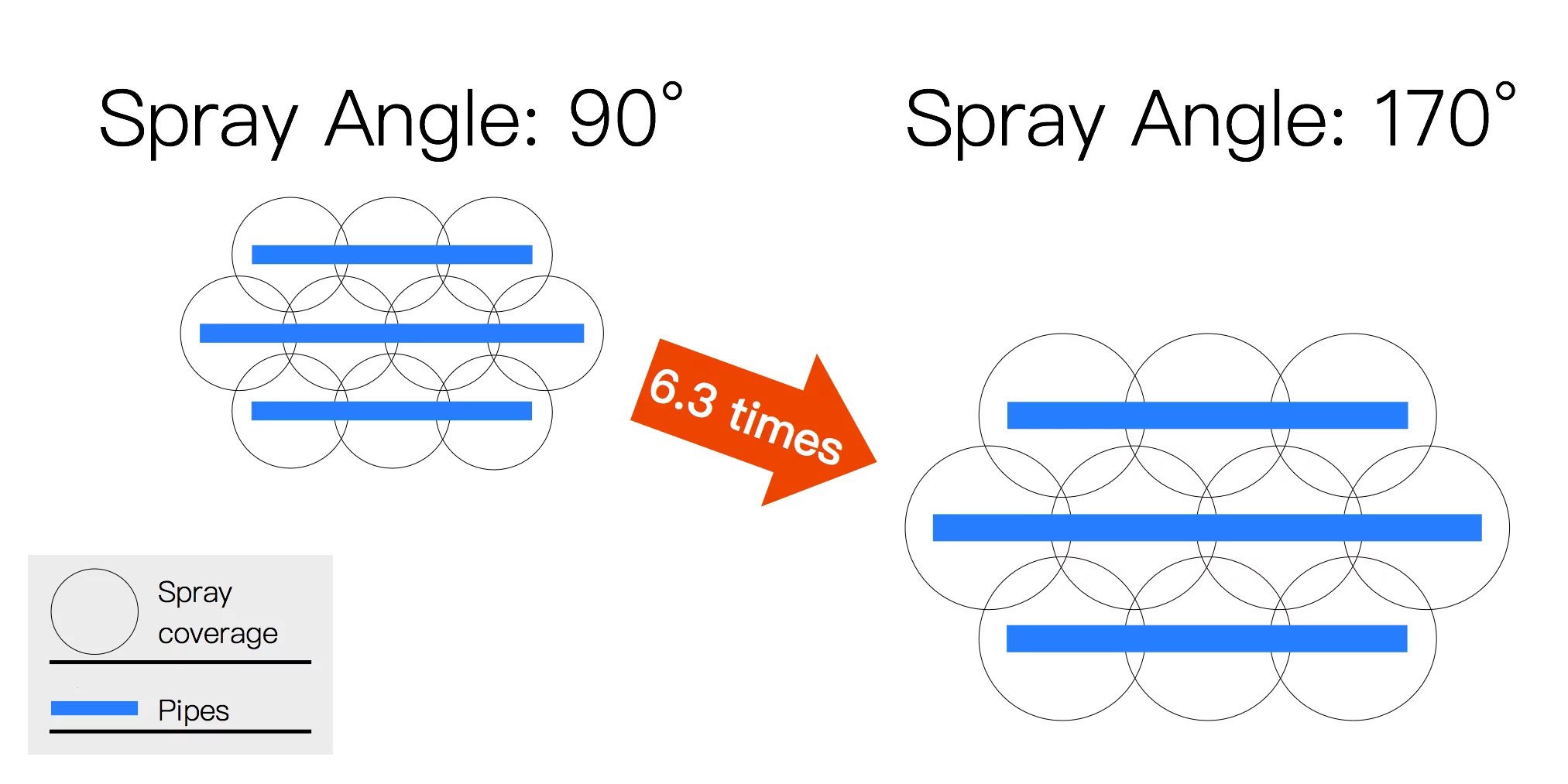
Tại khoảng cách 300 mm, khu vực bao phủ phun lý thuyết:
- Góc 90°: 60 cm, 0.28㎡ mỗi đơn vị
- Góc 170°: 150 cm, 1.76㎡ mỗi đơn vị (khoảng 6.3 lần)
4. 3 Quyết định khoảng cách quan trọng khi chọn góc đầu phun
1 ) Khoảng cách đến mục tiêu
Khoảng cách giữa đầu phun và khu vực mục tiêu, như tán cây của cây trồng, ảnh hưởng lớn đến sự phân bố của tia phun. Việc thiết lập khoảng cách tối ưu đảm bảo sự bao phủ hiệu quả đồng thời giảm thiểu sự lệch hướng và lãng phí. Các điều chỉnh nên xem xét loại phun và yêu cầu ứng dụng cụ thể để tối đa hóa hiệu quả.
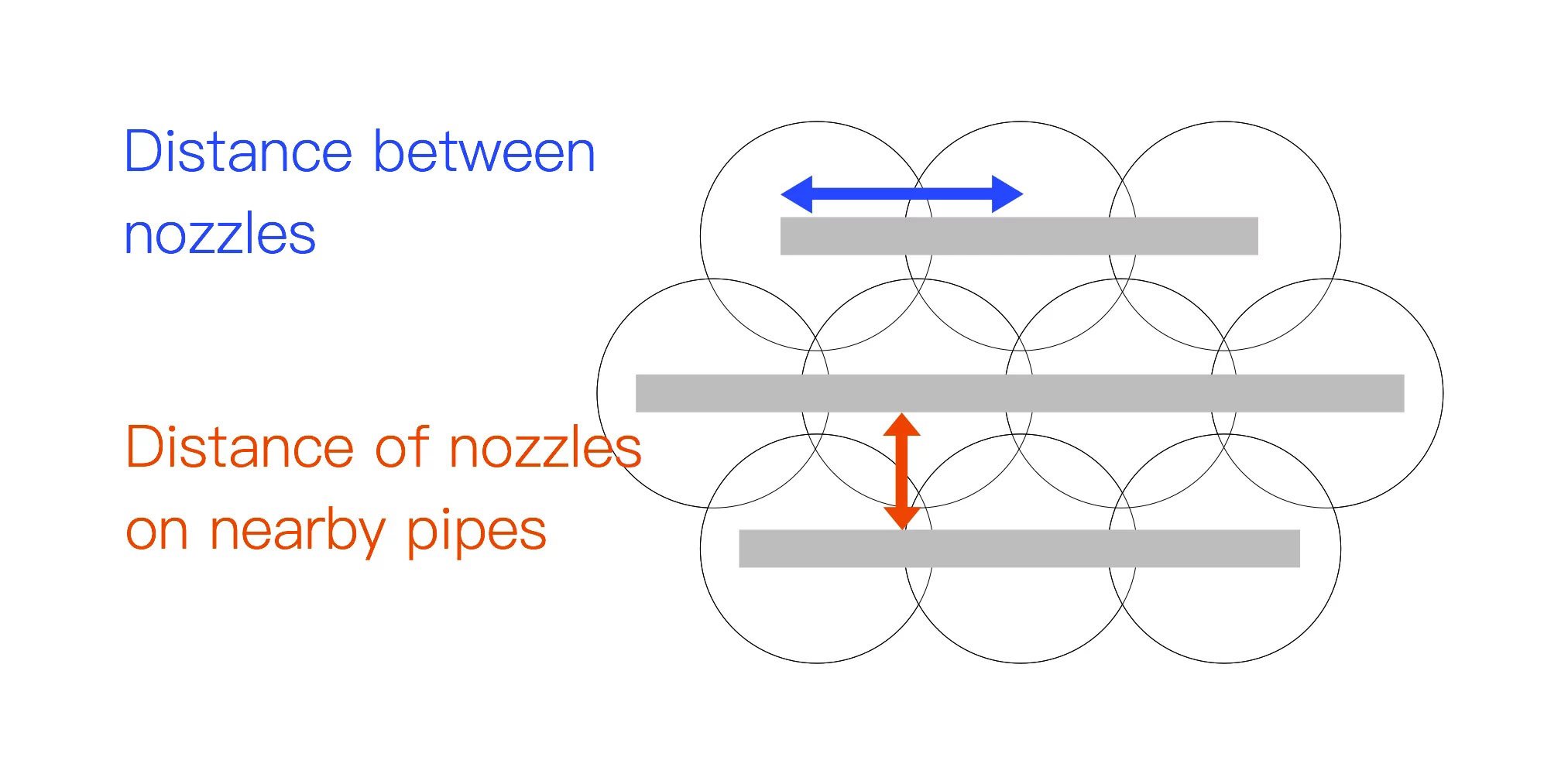
2 ) Khoảng cách giữa các đầu phun liền kề
Việc duy trì khoảng cách đúng giữa các đầu phun liền kề là rất quan trọng để đảm bảo sự bao phủ đồng đều trên khu vực mục tiêu. Khoảng cách không chính xác có thể dẫn đến sự chồng lắp các vùng phun hoặc bỏ sót các khu vực, ảnh hưởng đến hiệu quả tổng thể của quá trình phun. Khoảng cách này thay đổi tùy thuộc vào loại đầu phun và mẫu bao phủ mong muốn.
3 ) Khoảng cách giữa các thanh phun
Đối với các đầu phun không phải loại quạt, như đầu phun hình nón đặc, hình nón rỗng và đầu phun xoắn ốc, khoảng cách giữa các thanh phun đóng vai trò quan trọng trong việc lựa chọn góc phun và do đó ảnh hưởng đến mẫu bao phủ và hiệu quả của tia phun. Việc điều chỉnh đúng đắn đảm bảo sự chồng lắp tia phun tối ưu và phân bố đồng đều trên khu vực mục tiêu.
