This article examines the key role of ultrasonic flow meter probe installation in measurement accuracy, comparing Z, V, N, and W methods and showcasing LORRIC's clamps for easier installation. It also covers how pipe size, material, signal strength, and environment influence installation choices, with LORRIC providing proven installation strategies.
1. Installation Method of Ultrasonic Flowmeter Probe
Firstly, the installation of the ultrasonic flowmeter requires confirming that the two probes are 180 degrees apart on the axial section. What is meant by an axial section? Explanation must start from the concept of axial. Axial refers to the direction of the central axis of rotation of a cylinder, and an axial section is a longitudinal section passing through the axis.
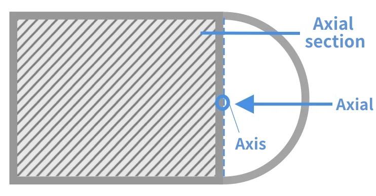
The two probes being 180 degrees apart on the axial section means that the two probes are directly opposite each other on the axial section, and it is necessary to confirm that the two probes are positioned opposite each other (as shown in the diagram below).
.png)
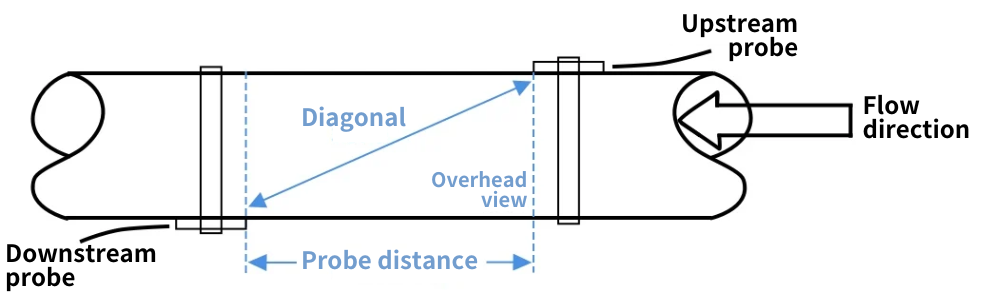
Next, confirm the diagonal measurement distance between the two probes (as shown in the diagram below).
2. Methods of Probe Installation
Installation methods include Z, V, N, and W, differentiated mainly by the probe's location and the path of signal reflection. More reflections allow for measuring smaller flows more accurately, but signal strength weakens with each bounce, increasing interference. The industry uses the RSSI parameter to indicate signal strength and the Q value for signal clarity. Both RSSI and Q values are essential for accurate measurement, with the recommended installation goal being to increase the Q value under a reasonable RSSI, ensuring clear and strong signal transmission.
1 ) Z Method
Typically used for pipe diameters over 300mm, where the ultrasonic signal doesn't reflect and thus retains stronger strength. This method avoids weak and distorted signals, but installing probes on opposite sides of the pipe can be challenging, often raising issues like ensuring probes are directly opposite on the axial cross-section and measuring the diagonal distance between probes accurately.
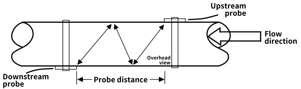
2 ) V Method
Commonly adopted for pipe diameters ranging from 50 to 300mm, where both probes are on the same side of the pipe, causing the ultrasonic signal to reflect once in a V shape. Since the probes are on the same side, it's easier to measure and achieve a balance in signal strength.
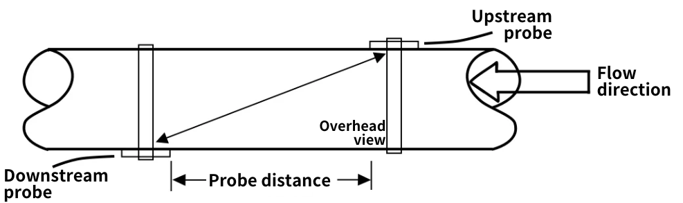
3 ) N Method
Typically used for pipes smaller than 50mm, the probes are placed on opposite diagonal sides of the pipe, making it difficult to measure the distance between probes. The ultrasonic signal reflects twice, achieving three paths, which extends the flight time and benefits the measurement accuracy in small pipes. In practical applications, this method is not recommended unless the V method cannot achieve an ideal signal state.
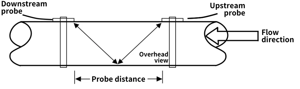
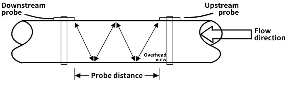
4 ) W Method
Used for pipes smaller than 50mm, where the ultrasonic signal reflects three times, achieving four paths, extending flight time and thereby enhancing measurement accuracy in small pipes. Although it's easier to measure probe distances with the probes on the same side, similar to the N method, the W method is generally not recommended unless the V method fails to adjust to an ideal signal state due to practical application challenges.
*Note: Operational environments vary significantly, and users must decide on the installation method based on the specific site conditions.
3. Overcoming the Challenges of Ultrasonic Flow Meter Probe Installation - LORRIC's Patented Probe Clamps
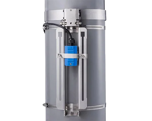
The Z and N methods, where probes are installed on opposite sides of the pipe wall, require the use of two track clamps, making it difficult to measure probe distances and challenging to install in larger pipe diameters. It's not easy to install ultrasonic flow meters at precise locations. LORRIC has innovated the traditional ultrasonic flow meter clamp installation process. Their specially designed clamps allow single-person installation by simply fitting the straps and placing the probes on the track, ensuring accurate alignment and signal transmission.
4. Factors Affecting Measurement Performance:
Large pipe diameters cause signal energy strength to inversely relate to the square of the distance, with RSSI decreasing over long distances. Z, V, N, and W methods see a sequential decrease in RSSI, and pipe material also impacts, as certain plastic materials particularly absorb sound waves. The nature of the liquid and surfaces prone to sound wave reflection affect RSSI, with many factors along the signal path influencing the received signal strength.
Generally, larger probes are more sensitive, mostly used for large pipe diameters. In smaller pipes, due to closer probe distances, large probes are less suitable and often result in installation challenges at optimal locations.