पैडल व्हील फ्लोमीटर कैसे काम करता है?
Paddle wheel flow meter measure flow by using fluid to drive the rotation of blades, with the rotational speed proportional to the flow rate. Suitable for measuring low-viscosity liquids like water, oil, and chemicals, these meters are characterized by moderate accuracy, quick response, and easy installation and maintenance. Due to direct contact with the liquid, regular cleaning and inspection are required.
Wider Detection Range
Traditional paddle wheel flow meter often have significant errors or cannot detect flow at low flow rates in the fluid inside the pipe. Upgrade your flow measurement capabilities with LORRIC's AxleSense technology! No more worries about inaccurate readings or missed low flow rates. Our advanced innovation ensures enhanced accuracy and a broader measurement range, spanning from 0.15 m/s to 10 m/s—double that of competing brands.
Bi-Directional Flow Detection
AxleSense's patented technology enables bidirectional flow detection by measuring paddlewheel rotation direction, overcoming the limitations of other brands that use Hall effect sensors, which can detect rotation but not direction. This technology also provides fluid flow direction information, positive/negative/net flow calculations, and a 14-day history of daily accumulations, optimizing operations and enhancing on-site management efficiency.
Real-Time Smart Detection
Provides clear paddle anomaly alerts, essential for Industry 4.0 integration. It quickly resolves flow issues by syncing with factory management systems. Built-in magnetic sensing checks paddlewheel magnet strength, ensuring consistent flow accuracy through regular monitoring and scheduled replacements.
Premium-grade pipe fitting: Built to last and leak-free perfection
Experience the pinnacle of durability with LORRIC's precision-turned pipe fittings. Crafted from extruded rod material, these fittings offer unwavering size consistency and a flawless, wave-free inner surface. The result? Reduced disturbances and higher measurement precision. With superior strength compared to injection-molded alternatives, our machined plastic pipe fittings eliminate concerns like flash, short shots, and weld lines. Say goodbye to compromises and embrace the reliability and quality you deserve.
Traditional plastic injection molding methods often result in uneven surfaces and wave-like patterns on the inner walls of tee fittings. This is because the melted plastic is compressed, causing greater shrinkage in thicker areas. As a consequence, the pipe's cross-sectional area becomes inconsistent, leading to unstable fluid flow and inaccurate calculations. Additionally, injection-molded fittings are prone to issues like flash, short shots, and weak weld lines, making them more susceptible to damage over time. In contrast, LORRIC's tee fittings are manufactured using a different approach, ensuring smooth and reliable performance while overcoming the limitations of conventional techniques.
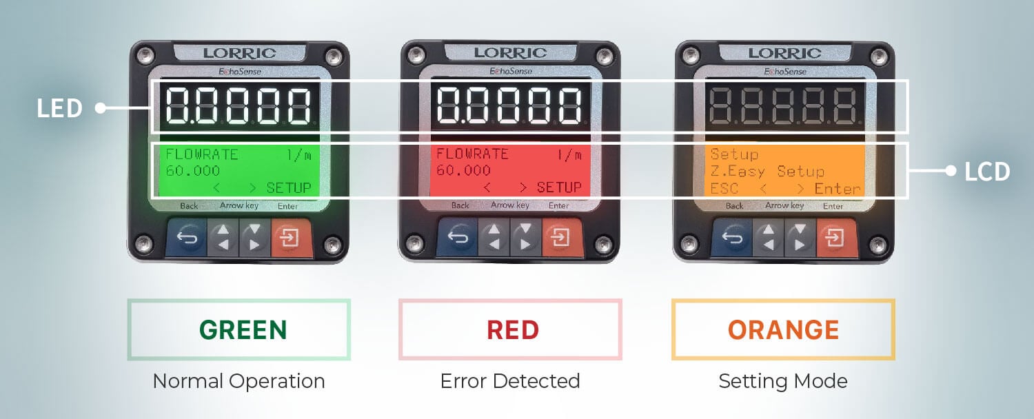
Dual LCD/LED screens for easy traffic and equipment status monitoring
- High-brightness large LED screen for easy long-distance flow number reading.
- LCD screen backlight with three-color warning light signal for visual monitoring of flow meter's normal and abnormal conditions.
Screen can be switched according to vertical or horizontal piping
Adjust the viewing direction of the screen according to the piping direction, which is convenient for flow monitoring in different piping situations.
Learn more: How to Install Paddle Wheel Flow Meter
Multiple Communication Outputs
FU-ES supports various communication modes like Analog output with self-powered 16-bit 4-20mA, Modbus RTU RS485, 2-wire photoelectric switch signal (compatible with NPN/PNP). No need for additional communication modules – we've got you covered!
Learn more:
•What is Analog Output
•What is Modbus RTU RS485
•What is Switch Signal
Pulse 2.0 Technology
Traditional pulse output paddle wheel flow meter use a constant K-value across the entire range, leading to higher errors, especially at varying flow rates. For instance, a conventional paddle wheel flow meter in a DN15 pipe outputs one signal every 90 degrees, with 106.55 pulses equaling 1L, regardless of flow speed.
LORRIC’s exclusive Pulse 2.0, powered by AxleSense technology, outputs one pulse per 0.01L, reducing errors by adjusting for different flow speeds.
Paddle Wheel Flow Meter FP-AS Series
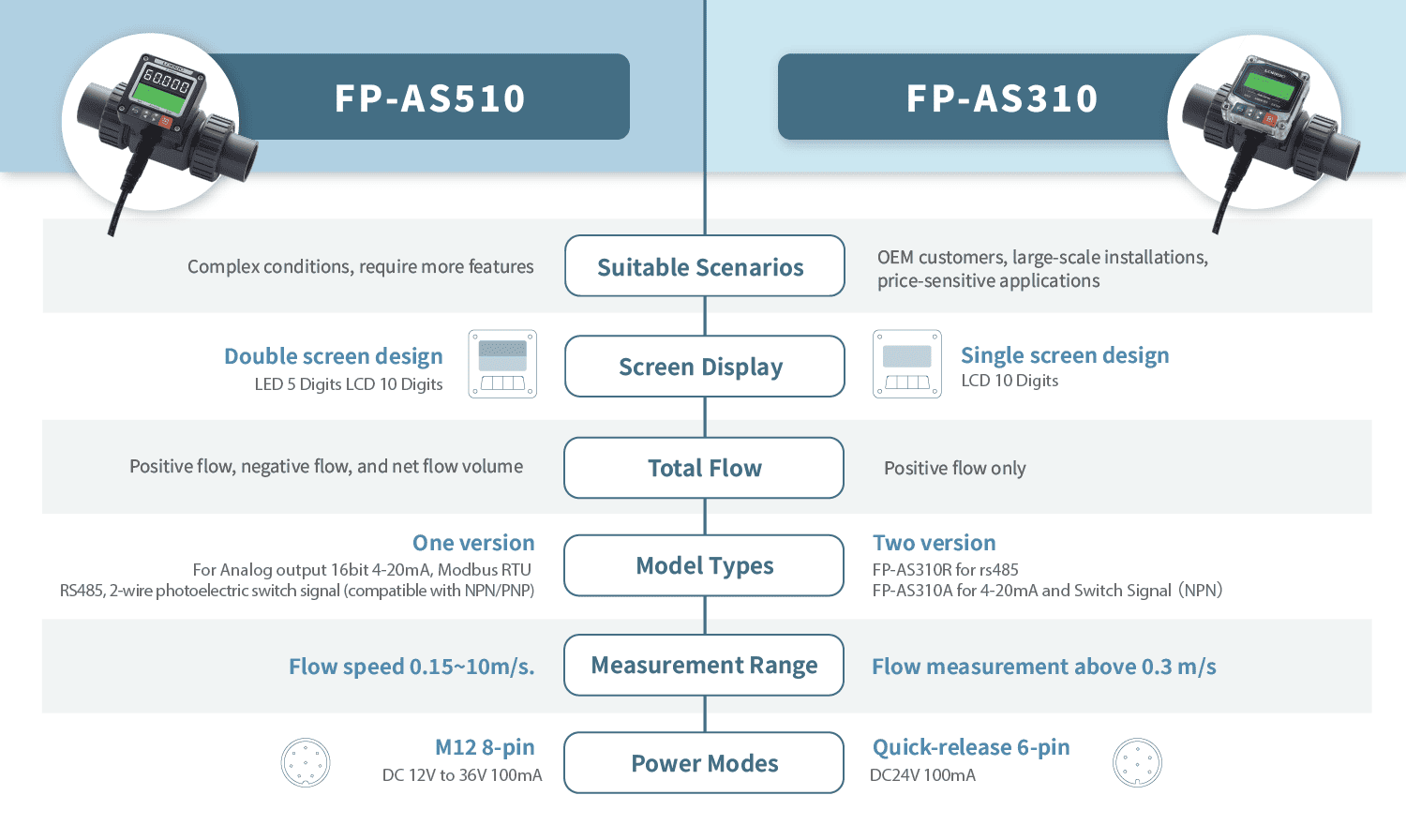
The FP-AS series offers two versions: FP-AS310, an entry-level model ideal for applications requiring multiple flow meter installations at a cost-effective price; and FP-AS510, which provides more advanced features, making it suitable for complex operating conditions.
Comparison with other principle flowmeters on the market
|
Variable area flowmeter |
Paddle wheel flowmeters |
LORRIC's Paddle wheel flowmeter |
Electromagnetic flowmeter |
Ultrasonic flowmeters |
Pipeline loss
|
Low
|
Low
|
Low
|
No |
No |
| Non-invasive install |
No |
No |
No |
No |
Yes123 |
| Precision |
Middle |
Middle |
Middle |
High |
High |
Bidirectional flow detectable
|
No |
No |
Yes |
Yes123
|
Yes |
| Blockages |
Possible |
Possible |
Possible |
Not possible |
Not possible |
| Applicable fluid |
Air / Liquid |
Liquid |
Liquid |
Conductive liquid |
Liquid |
| Cost |
Lowest-costs in small diameter pipe, cost increases with pipe diameter |
Low-costs, cost increases with pipe diameter |
Low-costs, cost increases with pipe diameter |
High-costs, cost increases with pipe diameter |
Middle-costs Cost does not increase with pipe diameter |
|
FP-P015 |
FP-P020 |
FP-P025 |
FP-P032 |
FP-P040 |
FP-P050 |
FP-P065 |
| Installation Method |
in-line
|
| Applicable Diameter |
| mm |
DN 15 |
DN 20 |
DN 25 |
DN 32 |
DN 40 |
DN 50 |
DN 65 |
| inch |
1/2" NPS |
3/4" NPS |
1" NPS |
1-1/4" NPS |
1-1/2" NPS |
2" NPS |
2-1/2" NPS |
| T-connector material |
UPVC / PPH / PVDF (Made to order)/ 316L Stainless Steel |
| Paddle material |
PVDF or PPH with embedded magnet + ceramic bearing and shaft
|
| Applicable fluid |
Various fluid with less impurities (<1%)
|
Applicable fluid maximum
dynamic viscosity |
300cSt *
|
| Fluid in pipes temperature |
UPVC : 0~50°C (32~122°F) / PPH : 0~90°C / PVDF:-20~140°C / ss316L:-20~100°C **
|
Device working
environment temperature |
-10~60°C (14~140°F)
|
| Velocity range |
± 0.3~10m/s Can extend to ± 0.15m ~ 10m/s ***
|
| Flow range |
| LPM |
1.8 -120.6 |
2.9 -188.5 |
4.4 - 294.5 |
6.8 -452.9 |
11.3 - 754.0 |
18.4 -1225.7 |
32.7 - 2179.0 |
| GPM |
0.47 - 28.4 |
0.83 - 49.86 |
1.35 - 80.81 |
2.33 -139.86 |
3.17 - 190.36 |
5.23 - 313.77 |
8.77 - 526.29 |
| Language |
English, Traditional Chinese, Simplified Chinese (Others customizable)
|
| Unit |
Metric: Liter, cubic meters, meters
Time: second, minute, hour, day
Imperial: foot, Cubic foot, Uk gallon, US gallon
|
| Display |
Double screen display :Large 5-Digit LED, 16x3 3-Color Backlight LCD display
|
| Display update cycle |
0.5s、1s
|
| Display resolution |
Maximum resolution 0.0001 (finest)
|
| Measurement accuracy |
±2.5% OR ****
|
| Linearity |
± 0.5 % FS (>0.3m/s)
|
| Reproducibility |
± 0.4 %
|
| Power supply |
DC 12V to 36V 100mA
|
| Power I/O Connector |
M12 8-pin connector (2 meters long)
|
| Input/Output |
Analog output with self-powered 16-bit 4-20mA
Modbus RTU RS485
Two-wire optocoupler switch signal (with 2 meters long signal line)
|
| Consumption current |
<200mA@12V when starting up and working stably (not included in the communication current)
|
| Protection circuit |
Power reverse connection protection, Power surge protection
|
| Waterproof level |
IP66 *****
|
| Transient data |
Instantaneous flow rate, instantaneous flow rate
|
| Cumulative data |
Volume accumulation (positive flow\negative flow\net flow)
Accumulated daily volume in the past 14 days (enable the date function after installing the date battery)
|
| Display digits |
ED 5 Digits (4 digits when negative value)
LCD 10 Digits (Not including sign and decimal point)
|
| Operation button |
4 Key touch buttons
|
| Calendar function battery |
CR2032
|
* The device is calibrated with water at normal temperature before leaving the factory. Using fluids with viscosities different from water may result in inaccurate calibration values and could affect the minimum and maximum flow rates.
** The working temperature range for each material is provided as a reference. Please use your design experience to make the final material selection.
*** The minimum flow value may vary slightly due to flow field factors specific to individual models.
**** The measurement accuracy is determined through laboratory testing with clean water at a controlled room temperature of 25°C. Actual usage conditions may introduce errors.
***** IP66 stands for 'Ingress Protection,' which signifies the degree of protection an electrical device's enclosure offers against foreign object intrusion. The first digit ('6') denotes full dust protection, while the second ('6') means no harm from high-pressure water splashes.
| FP-P015 |
| Size |
Connector |
Spec |
Material |
| 1/2" |
| Male Thread |
BSPT |
UPVC / PVDF |
| NPT |
UPVC / PVDF |
| Female Thread |
BSPT |
UPVC / PVDF |
| NPT |
UPVC / PVDF |
| Socket |
CNS |
UPVC |
| JIS |
UPVC |
| ANS |
UPVC |
| DIN |
UPVC |
| Butt Fusion |
ISO |
PPH / PVDF |
| Socket Fusion |
ISO |
PPH / PVDF |
| FP-P025 |
| Size |
Connector |
Spec |
Material |
| 1" |
| Male Thread |
BSPT |
UPVC / PVDF |
| NPT |
UPVC / PVDF |
| Female Thread |
BSPT |
UPVC / PVDF |
| NPT |
UPVC / PVDF |
| Socket |
CNS |
UPVC |
| JIS |
UPVC |
| ANS |
UPVC |
| DIN |
UPVC |
| Butt Fusion |
ISO |
PPH / PVDF |
| Socket Fusion |
ISO |
PPH / PVDF |
| FP-P032 |
| Size |
Connector |
Spec |
Material |
| 1-1/4" |
| Male Thread |
BSPT |
UPVC / PVDF |
| NPT |
UPVC / PVDF |
| Female Thread |
BSPT |
UPVC / PVDF |
| NPT |
UPVC / PVDF |
| Socket |
CNS |
UPVC |
| JIS |
UPVC |
| ANS |
UPVC |
| DIN |
UPVC |
| Butt Fusion |
ISO |
PPH / PVDF |
| Socket Fusion |
ISO |
PPH / PVDF |
| FP-P040 |
| Size |
Connector |
Spec |
Material |
| 1-1/2" |
| Male Thread |
BSPT |
UPVC / PVDF |
| NPT |
UPVC / PVDF |
| Female Thread |
BSPT |
UPVC / PVDF |
| NPT |
UPVC / PVDF |
| Socket |
CNS |
UPVC |
| JIS |
UPVC |
| ANS |
UPVC |
| DIN |
UPVC |
| Butt Fusion |
ISO |
PPH / PVDF |
| Socket Fusion |
ISO |
PPH / PVDF |
| FP-P050 |
| Size |
Connector |
Spec |
Material |
| 2" |
| Male Thread |
BSPT |
UPVC / PVDF |
| NPT |
UPVC / PVDF |
| Female Thread |
BSPT |
UPVC / PVDF |
| NPT |
UPVC / PVDF |
| Socket |
CNS |
UPVC |
| JIS |
UPVC |
| ANS |
UPVC |
| DIN |
UPVC |
| Butt Fusion |
ISO |
PPH / PVDF |
| Socket Fusion |
ISO |
PPH / PVDF |
| Flange |
JIS 10K |
UPVC |
| FP-P065 |
| Size |
Connector |
Spec |
Material |
| 2-1/2" |
| Butt Fusion |
ISO |
PPH / PVDF |
| Socket Fusion |
ISO |
PPH / PVDF |
| Socket |
CNS |
UPVC |
| JIS |
UPVC |
| ANS |
UPVC |
| DIN |
UPVC |
| Flange |
JIS 10K |
UPVC |
⚠ Safety instructions:
1. After the warranty, the electronic components of the product will age due to time and operating environment. Under long-term use, please replace the new product according to the condition of the product.
2. Do not operate the product under an Orange or Red LCD Backlight for a long time. Product damage and related losses may occur.
Conditions and Disclaimer:
CONDITIONS: Equipment sold by LORRIC is not intended to be used, nor shall it be used:
(1) As a "Basic Component" under 10 CFR 21 (NRC), used in or with any nuclear installation or activity; or (2) In medical applications or used on humans. Should any product(s) be used in or with any nuclear installation or activity, medical application, used on humans, or misused in any way, LORRIC assumes no responsibility as set forth in our basic WARRANTY/ DISCLAIMER language, and, additionally, purchaser will indemnify LORRIC and hold LORRIC harmless from any liability or damage whatsoever arising out of the use of the product(s) in such a manner.
DISCLAIMER: Please be aware that magnetic fields or residual magnetism may cause interference to the flowmeter which may result in damage if they are used near the installation site. The purchaser must determine the applicability of the product for its desired use and assumes all risks in connection therewith. LORRIC assumes no responsibility or liability for any omissions or errors in connection with the use of its products.
The alarm used to detect paddle damage or loss is intended to assist on-site operators to find out what is causing equipment abnormalities. Because there are a myriad of variables involved with on-site operation and magnetic fields that come from other equipment, the alarm function is liable to fail. Please do not take the alarm function as a single source for monitoring your flow system. Please contact LORRIC for advanced help.
Please place your order according below information.
- The whole set of paddle wheel flowmeter contains: Device, Paddle set, T-connector.
- Select the flowmeter device and cable connector ( Order code example: FP-AS510 (R) )
- Choose the T-connector + paddle set based on size, materials, type and pipe specification (Example: FP-P050CUAV)
- For ordering the whole set, combine both codes altogether
- Order code example: FP-AS510 (R) + FP-P050CUAV
(Download the catalog for more details.)
Size
| UPVC pipe - union diameter size(mm) |
|
A |
B
|
C
|
D
|
E
|
F
|
G
|
H
|
| ½" |
164 |
100 |
27.6 |
36 |
62.3 |
46.2 |
115.7 |
86.2 |
¾"
|
168 |
100 |
32.6 |
41.9 |
62.3 |
50.5 |
115.7 |
&85.7 |
1"
|
168 |
100 |
40.6 |
50 |
62.3 |
60 |
115.7 |
85.7 |
1¼"
|
210 |
114 |
50.2 |
59.6 |
65 |
75.6 |
127 |
89.2 |
1½"
|
218 |
120 |
56 |
65.7 |
70 |
83 |
134 |
92.5 |
2"
|
269.5 |
133.3 |
72 |
81 |
81 |
99.7 |
148.8 |
99 |
| UPVC pipe - spigot pipe diameter size(mm) |
|
A |
B
|
C
|
D
|
E
|
F
|
| 2½" |
160 |
70 |
76 |
92 |
106.5 |
152.5 |
| Device size(mm) |
| I |
J |
| 63 |
63 |
| Connector (mm) |
| K |
L |
| 47.8 |
30.0 |
Applications

Semiconductor
Flow meters monitor chemical liquids and pure water treatment fluids supply; nozzles control the spraying of chemical liquids to ensure process purity and stability.
PCBs
Flow meters in PCB electroplating, developing, and etching processes monitor precise chemical and cleaning fluid flow; nozzles control chemical coating and rinsing

Wastewater Treatment
Flow meters monitor the flow of inlet and outlet water, enhancing treatment efficiency and accuracy; nzzles spray chemicals in wastewater treatment, meeting environmental standards

Purified Water Industries
Flow meters monitor water usage at each stage to control process efficiency; nozzles optimize water spray to ensure water purification efficiency and reduce treatment costs

Car Wash
Flow meters ensure cleaning efficiency and reduce water wastage; nozzles uniformly distribute water, enhancing the cleaning effect while simultaneously reducing water consumption

AC
Flow meters monitor and control cooling and hot water flows, tracking chiller energy use; nozzles balance water flow in these systems, enhancing efficiency
Discover the Power of FP-AS510 in Just 3 Minutes!