The Relationship Between Nozzle Pressure, Orifice Size, and Flow Rate
The flow rate of a nozzle is closely related to the orifice size and pressure. Both an increase in pressure or orifice size will result in a higher flow rate, but this increase is not linear. In fact, under the same pressure, the flow rate is proportional to the square of the orifice diameter. Similarly, with a fixed orifice size, the flow rate is proportional to the square root of the pressure.
For the same nozzle model from LORRIC, various flow rate options are available. This is achieved by designing different orifice sizes and matching pressure ranges for the same nozzle. In other words, customers can select the appropriate nozzle specifications by referencing the flow rate code and pressure to meet their requirements.
This article will guide readers through understanding the relationship between flow rate, pressure, and orifice size.
1. The Relationship Between Nozzle Pressure and Flow Rate
When the pressure increases, the flow rate increases proportionally to the square root of the pressure. But why is this the case? The flow rate of a nozzle is determined using the following formula:
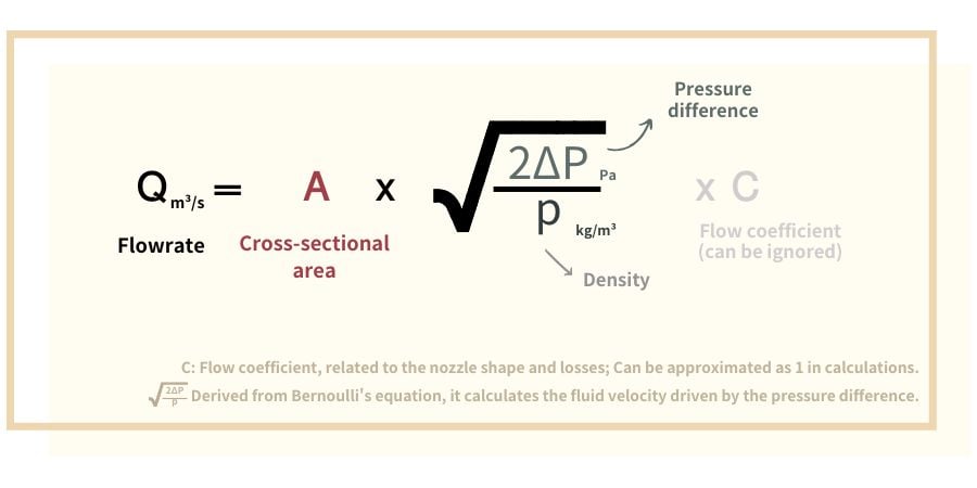
• So, how does the flow rate change when the pressure increases?
From the formula above, we can see:
When the pressure increases, the flow rate also increases, but not linearly. Instead, it follows a square root relationship.
If the pressure increases from 2 bar to 8 bar (4 times), the flow rate will only become √4 = 2 times the original.
In other words:
Flow rate Q is proportional to the square root of the pressure difference ΔP.
Thus, we can describe the relationship between flow rate Q and pressure P as:
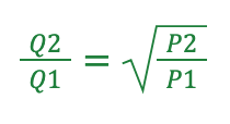
This way, we can simply use the relationship between flow rate and pressure difference to calculate values. For example, when changing nozzle operating conditions (such as flow rate), this formula can be used to determine the required pressure change or vice versa to find the flow rate under different pressures.
• I have a nozzle and want to calculate its flow rate under different pressures. How do I do that?
Assume a nozzle has a flow rate of 3.91 m³/s at a pressure of 3 bar. What is the flow rate at a pressure of 100 bar?
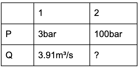
We are solving for the flow rate at 100 bar (denoted as Q2). Knowing that the flow rate is proportional to the square root of the pressure, we substitute the values into the formula:
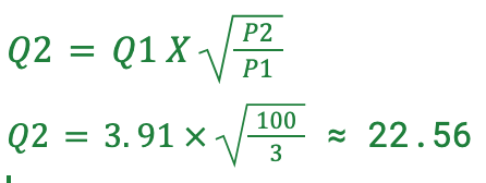
The flow rate at 100 bar can be calculated to be approximately 22.56 m³/s.
[2]
2. The Effect of Nozzle Orifice Size on Flow Rate
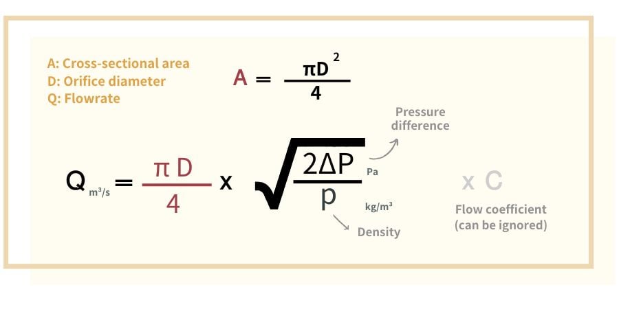
It can be observed that under the same pressure,
flow rate Q is proportional to the square of the orifice diameter D^2
Based on the assumption that flow rate is proportional to the square of the orifice diameter, we can calculate the flow rate using the following formula:
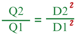
Example Calculation:
How can we calculate the flow rate for nozzles with different orifice sizes under the same pressure?
Given that when the orifice diameter is 2 mm, the nozzle flow rate is 10 L/min, what would the flow rate be if the orifice diameter is increased to 4 mm?
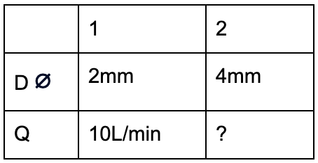
Substitute the known values:

It can be calculated that when the orifice diameter is 4 mm, the nozzle flow rate is approximately 40 L/min.
3. Misconception: Selecting Nozzles Based Solely on Orifice Diameter
“Orifice Diameter Does Not Equal Spray Performance”
As outlined in the previous sections, the spray performance of a nozzle is influenced by multiple factors, including orifice diameter, pressure, and flow rate.
Non-specialized nozzle sales platforms often use orifice size as the sole specification. However, in reality, the flow rate and spray angle of a nozzle cannot be determined by orifice size alone. For example, the elliptical orifice of a fan-shaped nozzle makes it difficult to intuitively define its diameter. Even for nozzles with the same 1 mm orifice diameter, their flow rates, spray angles, and impact distribution can vary significantly.
When designing nozzles, professional manufacturers prioritize understanding the customer’s desired performance. Our nozzles come with reference charts that correlate spray angle and flow rate with pressure, allowing customers to make an initial selection. If the actual spray effect does not meet expectations during usage, we do not immediately suggest increasing or decreasing the orifice size. Instead, we investigate the distribution pattern, identify on-site issues, and evaluate whether a change in nozzle model could improve the result. By considering multiple factors, we aim to achieve the customer’s desired spray performance.