The market offers hundreds of valve types. However, they can be broadly categorized into three types based on their motion: linear motion valves, rotary motion valves, and quarter-turn valves. Here are 11 common valves categorized by their motion type:
The opening and closing motion of a linear motion valve follows a straight line. The valve stem moves up and down within the valve body to open or close the valve, allowing the valve disc to tightly contact the seat. This typically results in good sealing performance. Common linear motion valves include:
a. Check Valve
Check valves, also known as non-return valves, are primarily used to prevent fluid backflow. They come in various types and are widely used in hydraulic systems. Due to their compact size, simple structure, and low cost, they are commonly found in household applications.
| Advantages |
Disadvantages |
| 1. Prevents fluid backflow. |
1. May affect system pressure. |
| 2. Simple structure and low cost. |
2. Only suitable for unidirectional flow. |
| 3. Wide range of applications. |
|
| 4. Low maintenance requirements. |
|
| 5. Operates automatically. |
|
[3]
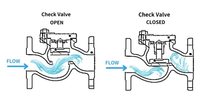
As shown in the diagram, the check valve operates as follows: fluid pressure pushes the valve open, allowing fluid to pass through. If the fluid attempts to flow backward, the valve closes, and the greater the backflow pressure, the better the seal. Check valves typically use a spring or gravity to close and do not require manual operation.
b. Diaphragm Valve
Diaphragm valves control fluid flow by using a flexible diaphragm to seal off the flow path. These valves are ideal for applications requiring corrosion resistance, making them commonly used in the chemical industry to handle various chemicals, solvents, and corrosive media.
Diaphragm valvesare also frequently utilized in the food and pharmaceutical industries, as they effectively prevent cross-contamination and ensure the hygiene and safety of the fluids.
[4]
| Advantages |
Disadvantages |
| 1. Excellent sealing capabilities. |
1. Limited pressure tolerance. |
| 2. High corrosion resistance, suitable for corrosive fluids. |
2. Not suitable for high-temperature environments. |
| 3. No dead space, minimizing residue buildup and meeting high hygiene standards. |
3. Narrow range of flow regulation. |
[5]
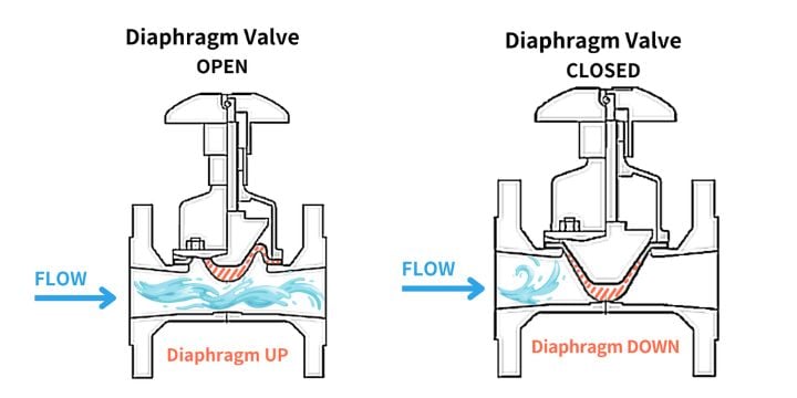
As shown in the diagram, a diaphragm valve consists of an elastic diaphragm within the valve body and bonnet. When the valve stem lifts, the diaphragm is raised, allowing fluid to flow through. Lowering the stem causes the diaphragm to block the inlet, stopping the flow. The separation of the actuating mechanism from the fluid by the diaphragm ensures excellent sealing, making diaphragm valves ideal for corrosive fluids, fibrous slurries, radioactive fluids, or other applications requiring contamination-free operation.
c. Globe Valve
Globe valves, also known as stop valves, regulate flow and pressure and are versatile. Originally named for their spherical shape, they are now sometimes called stop valves to avoid confusion with ball valves.
Globe valves commonly used in heat exchange systems, globe valves allow direct fluid flow, making them suitable for high-viscosity fluids. They are ideal for water treatment, chemical, petroleum, and steam systems, as they prevent fluid accumulation and solidification inside the valve.
[6]
| Advantages |
Disadvantages |
| 1. Low resistance due to straight flow path. |
1. Operating temperature is limited by seat material. |
| 2. Available in various sizes, offering wide application range. |
2. Higher flow resistance compared to other valves. |
| 3. Suitable for frequent operation. |
3. Relatively heavy in weight. |
| 4. Low friction loss, ensuring long service life. |
|
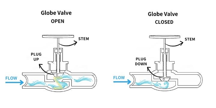
Operation is as follows: turning the handwheel raises the valve stem. When the ball valve opens, the core moves up, allowing fluid to pass. The fluid follows a mirrored Z-shaped path inside the valve, entering low and exiting high, which increases resistance and reduces pressure. To close the valve, the core descends to tightly contact the valve seat, forming a seal to stop fluid flow.
In operation, fluid flows directly from the inlet to the outlet. This linear flow path reduces vortices and stagnation within the valve, helping to prevent high-viscosity fluids from solidifying or accumulating. Ball valves are commonly used in water treatment systems, chemical and petroleum industries, and steam systems.
[7][8]
d. Needle Valve
Needle valves feature a needle-shaped plunger that precisely fits into the valve seat, allowing for fine control of fluid flow at low pressures. Needle valves are ideal for applications requiring small or constant low flow rates, such as vacuum systems, filling gas tubes, gas lasers, and similar equipment, as well as controlling idle fuel flow in carburetors.
*Vernier Effect in Needle Valves: Due to the conical shape of the needle valve core, as the control moves axially (i.e., the core moves in and out), a diameter difference is created between the needle valve and the seat. This vernier effect, with minimal radial change, is a key mechanism for the needle valve's precise flow control.
| Advantages |
Disadvantages |
| 1. Precise control of small flow rates. |
1. Not suitable for high flow rates. |
| 2. Suitable for low-pressure operations. |
2. Higher pressure loss. |
| 3. Can be used in vacuum systems. |
|
| 4. Compact structure with good sealing capabilities. |
|
[9][10]
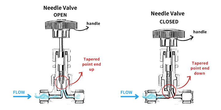
The needle valve structure is shown below. It has a relatively small orifice with a long conical seat that can be screwed in and out to change the orifice opening. The screw end has a needle-like plunger that fits completely with the seat when closed, allowing for the regulation of very fine flow rates. Due to the height limitation of the valve body, fluid pressure loss is significant, and the narrow piping increases the risk of damage from suspended solids.
Rotary Motion Valve opens and closes by rotating around an axis. The valve core usually operates in a rotating manner to open or close the flow path
a. Ball Valve
Ball valves control fluid flow using a spherical ball with a hole through its center. They offer excellent sealing performance and require minimal maintenance. Their simple operation makes them ideal for applications requiring quick shut-off and reliable sealing. Ball valves are widely used in various settings, including industrial oil and gas pipelines, chemical processes, and residential water systems.
[11]
| Advantages |
Disadvantages |
| 1. Capable of handling high pressure and high flow rates. |
1. Potential for sediment buildup between the ball and seat. |
| 2. Excellent sealing performance. |
2. Requires higher operating torque, possibly needing additional actuation mechanisms. |
| 3. Low flow resistance and easy maintenance. |
3. Generally larger and heavier in size. |
| 4. Can be used for flow control and diversion. |
|
[12]
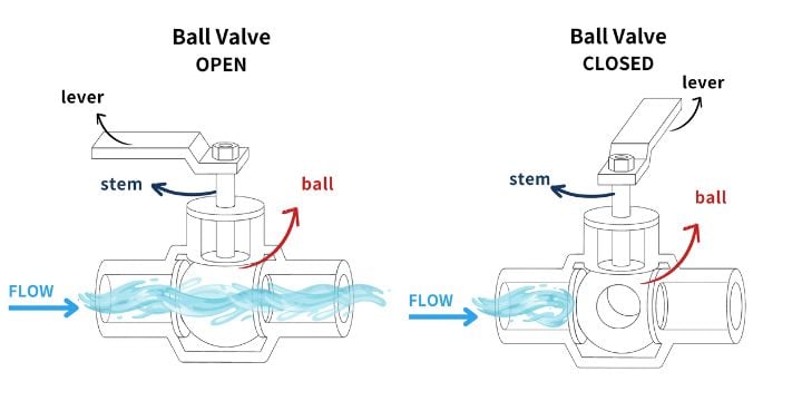
A ball valve has a hollow, ball-shaped core with a bore the same diameter as the pipeline. The handle turns the valve stem to rotate the core. When the bore aligns with the flow path, fluid passes through. To close the channel, a 90-degree turn of the handle blocks the fluid flow.
[13][14]
b. Butterfly Valve
Butterfly valves, or flap valves, have a simple design and operate quickly by rotating a disc to control flow. They are suitable for managing large volumes of liquids or gases at low pressures. These valves are versatile and can handle various media, including water, oil, steam, and corrosive fluids. Common applications include water treatment, chemical and petrochemical industries, HVAC systems, and agricultural irrigation.
There are several types of butterfly valves, each suited for different pressures and applications:
i. Concentric butterfly valve: This type has a flexible rubber seat with a metal disc, suitable for the lowest pressure ratings.
ii. Double-offset butterfly valve (high-performance or double-eccentric): The seat and disc use different materials, allowing operation across a wider range of temperatures and pressures.
iii. Triple-offset butterfly valve (triple-eccentric): Features a laminated or solid metal seat, ideal for high-pressure systems and harsh environments, commonly used in industrial and energy sectors.
[15][16]
| Advantages |
Disadvantages |
| 1. Quick operation, ideal for frequent use. |
1. Non-linear flow, causing uneven pressure. |
| 2. Compact, lightweight, and easy to operate. |
2. Less effective sealing. |
| 3. Good flow control. |
3. Can vibrate or make noise at high speeds. |
| 4. Low pressure drop when fully open. |
4. Not suitable for extreme temperatures or high-pressure conditions. |
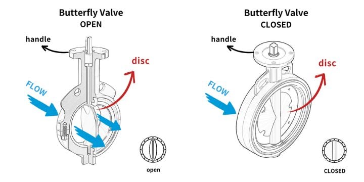
As shown, a butterfly valve consists of a rotating disc typically located at the center of the valve body. During operation, the circular disc rotates around an axis with a maximum angle of 90 degrees, adjusting the medium flow by changing the angle. Since the disc is always present in the fluid, it increases flow resistance, causing local pressure loss.
c. Pressure Reducing Valve
A pressure relief valve is primarily a safety valve used to control or limit system pressure, preventing equipment failure, explosions, or fires due to excessive pressure. It operates through a spring or pressure adjustment device within the valve that controls opening and closing. This safety valve automatically opens at a set pressure value to release excess pressure. Pressure relief valves are crucial in various industrial applications, especially in high-pressure operations, ensuring industrial safety.
A pressure relief valve is designed with a preset pressure at which it automatically opens when the system pressure reaches a certain level. This setting is typically operated by a valve spring or other mechanical elements such as weights or pilot valves.
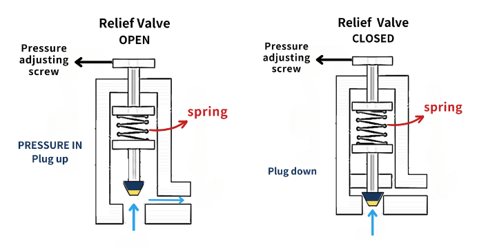
The diagram shows a spring-operated pressure relief valve. When the system pressure exceeds the set threshold, the increased pressure pushes the valve core, compressing the spring and opening the valve. This releases the excess pressure or fluid, lowering the system pressure. Once the pressure returns to a safe range, the spring pushes the valve core back to its initial position, closing the valve.
d. Gate Valve
Gate valves use a movable gate to stop or allow flow, not to regulate it. They have low flow resistance when fully open and require minimal effort to operate. However, they need a longer time to open or close fully due to the gate's travel distance.
[17]
| Advantages |
Disadvantages |
| 1. Excellent fluid shut-off capability. |
1. High-pressure differentials can cause water hammer. |
| 2. Near-zero flow resistance when fully open. |
2. Long operation time to open or close. |
| 3. Suitable for various fluids, including liquids, gases, and steam. |
3. Large size, requiring more space. |
| 4. Can withstand high pressure and temperature. |
|
[18]
Gate valves come in various types, typically featuring a simple structure without specific inlet or outlet installation requirements. As shown, they have a rising stem operated by a handwheel or motor, lifting the gate to open the flow path.
Gate valves are suitable for larger pipe diameters. However, due to possible gaps or wear between the valve and the sealing surface, slight leakage may occur even when fully closed. Additional measures may be needed in applications requiring strict fluid sealing.
Right-angle rotary valves operate with a 90-degree rotation, moving the valve core horizontally or vertically to open or close the flow path. These valves are ideal for applications requiring quick operation, often used in remote control and automation systems. Common right-angle rotary valves include solenoid valves and pneumatic valves.
a. Solenoid Valve
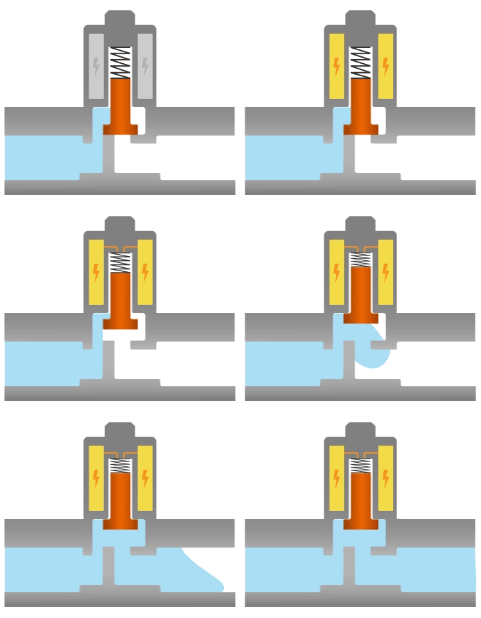
Solenoid valves use an electric current in a coil to create a magnetic field, controlling the valve's operation. They enable automated and remote control, making them ideal for applications like on-off control, test plant systems, and process control. Solenoid valves are also used in hydraulic jacks and truck hydraulic cylinders.
[19][20]
| Advantages |
Disadvantages |
| 1. Remote and quick control, ideal for automation. |
1. Only for clean media, not for viscous or particulate fluids. |
| 2. Compact, space-saving and easy to install. |
2. Low pressure tolerance. |
| 3. Low power consumption. |
3. Needs stable power; won't work during outages. |
| 4. Precise flow and direction control. |
4. Requires regular maintenance for seals and coils. |
In a Normally Closed (NC) solenoid valve, the valve remains closed when the solenoid coil is not energized. Inside the NC solenoid valve, there is an armature surrounded by a solenoid. A spring connects the armature to a plunger. When not energized, the plunger blocks the passage. When current is applied, a magnetic field is generated inside the solenoid valve, pulling the plunger up and opening the passage, allowing fluid to flow through. Once the current is turned off, the plunger returns to its original position, blocking the fluid flow.
[21]
b. Pneumatic Valve
Pneumatic valves, or air-operated valves, use air pressure to control fluid flow, suitable for high-pressure and high-temperature conditions. They are used in the energy sector for oil, gas, and water control, in the chemical industry for reactors and storage tanks, and in medical devices like ventilators and gas supply systems.
*The principle of a pneumatic valve is simple: it opens when there is no air and closes when there is air.
[22]
| Advantages |
Disadvantages |
| 1. High safety, operates in harsh conditions. |
1. Requires a compressed air system, high initial installation cost. |
| 2. Fast opening/closing, suitable for quick response applications. |
2. Needs filtration and drying equipment to protect components. |
| 3. Strong force, ideal for large valves and high-pressure systems. |
3. Limited control precision, not ideal for exact flow control. |
| 4. Simple, durable design, good for frequent use. |
4. Can generate noise during exhaust. |
A pneumatic valve consists of two main parts: the bottom mechanical device and the top pneumatic device. Inside the mechanical device is the valve disc, which moves up and down to open or close the valve, similar to a stop valve (ball valve). The valve is covered by a bonnet, which can be opened for internal maintenance. The mechanical device is connected to the top device by a vertical spindle with a pointer that indicates whether the valve is open or closed. The top device contains a pneumatic actuator. When gas is injected through the port, the air pressure compresses the diaphragm and spring, pushing the valve core down to close the passage, preventing fluid flow. Conversely, when air is released, the spring expands, the valve core moves up, and the passage opens, allowing fluid to flow through.
[23][24]