Overview
- RS485 is a hardware architecture that specifies only the electrical characteristics of transmitters and receivers, without endorsing any particular transmission protocol.
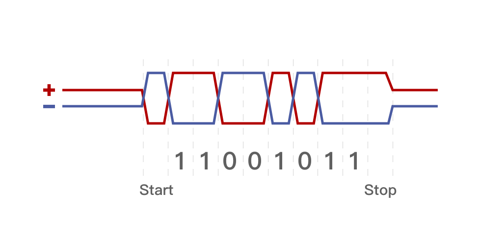
- RS485 transmits binary signals by generating high and low voltages, representing binary 0s and 1s (on and off), enabling efficient long-distance communication in electronically noisy environments.
- Devices utilizing RS485 can communicate with central control systems using communication protocols such as Modbus and ASCII.
1. What is RS485?
RS485 is a standard serial communication interface, also known as TIA-485(-A) or EIA-485. It defines the electrical characteristics for 2-wire, half-duplex, multi-point communication using twisted pair cables. RS485 supports multiple devices on the same bus and excels in long-distance, noise-prone environments.
"RS485 is Not a Communication Protocol"
RS485 only specifies electrical characteristics, like voltage and signal transmission. It does not define data encoding, decoding, or transmission formats, which are handled by communication protocols.
[1]
As RS485 doesn't define communication protocols like speed or format, it must be paired with protocols (e.g., Modbus, ASCII) for data transmission and interpretation. RS485 sends differential signals, where high and low voltages represent binary 0 and 1, allowing for efficient, long-distance communication in noisy environments.
In most cases, RS485-based devices can employ communication protocols such as Modbus and ASCII to establish communication with a central control system. To illustrate, let's consider LORRIC's paddle wheel flowmeter, which utilizes Modbus as the underlying protocol for defining various signal transmissions. The flowmeter leverages RS485 for signal transmission and is connected in a serial configuration with the customer's central control system. Through appropriate programming and configuration settings within the central control system, relevant flow measurement data can be read from the flowmeter.
2. RS485 vs RS232
RS485 improves on several limitations of RS232, such as transmission distance, multi-point communication, and noise resistance. However, the two are not direct replacements. RS232 is better suited for simple, short-distance, point-to-point connections, like communication between a computer and external devices. In contrast, RS485 is commonly used in industrial and building automation environments, where long-distance, multi-device, and stable communication are required.
| Communication Interface |
RS232 |
RS485 |
| Transmission Method |
 Point-to-point communication, can connect only two devices at a time. Point-to-point communication, can connect only two devices at a time. |
 Multi-point communication, depending on the chip level, one bus can connect 32, 128, or 256 transmitters and receivers. Multi-point communication, depending on the chip level, one bus can connect 32, 128, or 256 transmitters and receivers. |
| Transmission Distance |
Within 15 meters |
Maximum transmission distance up to 1200 meters |
| Interference Resistance |
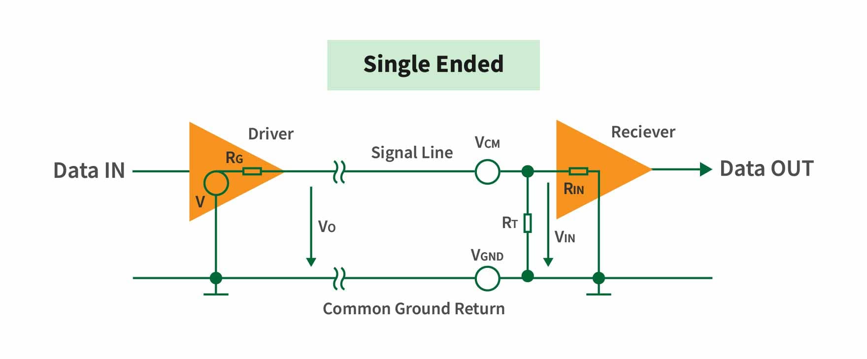
Single-ended signal, large voltage range, weaker resistance to external electromagnetic interference. |
Differential signal transmission, small voltage range, communication through voltage difference between two wires, excellent interference resistance. |
| Communication Speed |
Maximum transmission rate is 20 kB/s |
The shorter the distance, the higher the rate, with a maximum transmission rate of up to 10 Mbps |
| Cost |
Low |
High |
| Design |
Simple |
Complex |
3. RS485 Wiring Solution
1 ) RS485 Connection for Multiple Devices
RS485 provides a means of interconnecting multiple devices in a series using a twisted pair of wires to facilitate data exchange. It offers two primary wiring methods: two-wire half-duplex and four-wire full-duplex. While four-wire full-duplex exists, it is less prevalent in current applications, with the two-wire half-duplex configuration being the predominant wiring method in use today.
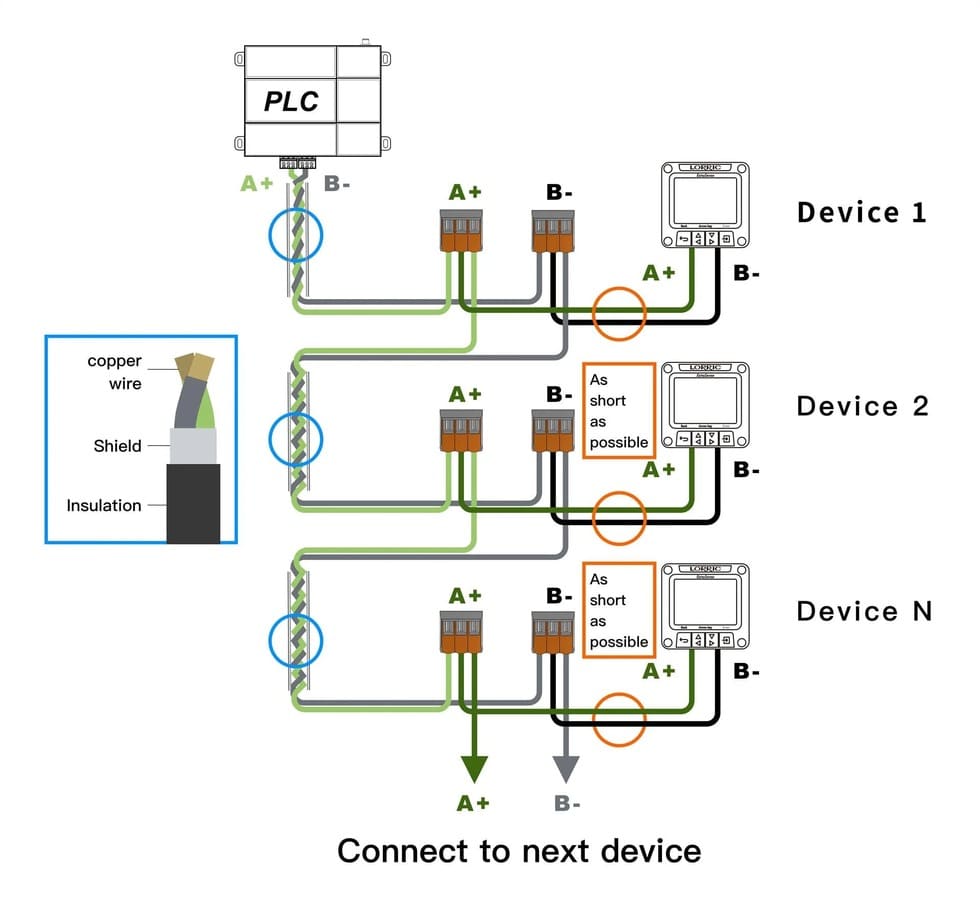
The picture shows the RS485 wiring scheme, including device interconnection, twisted pair cable structure, and signal transmission.
- Devices (Device 1, Device 2, Device N) are connected in series, forming a daisy chain topology. Each device's A+ and B- ports are connected to the corresponding ports of the next device using twisted pair cables. The wiring method uses A+ and B- lines, representing a two-wire half-duplex configuration, which is the most commonly used wiring method in RS485.
- The left side of the image shows the structure of the twisted pair cable, including copper wire, shielding, and insulation. This cable structure helps maintain stable data transmission in electrically noisy environments. It should be noted that the connection wires between each device should be kept as short as possible to minimize signal attenuation and interference, improving communication reliability.
- The entire daisy chain network is ultimately connected to a PLC (Programmable Logic Controller), facilitating data exchange between multiple devices and the central control system. Using the RS485 standard, signals are transmitted through A+ and B- lines, with high and low voltages representing binary 1 and 0 (on and off), ensuring reliable data communication.
2 ) RS485 Wiring Recommendations
- Use shielded 24AWG twisted pair cables with 485+ and 485- twisted together. Connect devices in a daisy-chain and avoid ring or star layouts. Keep RS485 cables separate from high-voltage lines to prevent interference.
- In noisy environments, implement a retry mechanism in the software to handle interference. Use short cables to minimize noise, and ground the shielding by connecting it to the main communication line’s shield.
3 ) When to Use Termination Resistors with RS485
➤ Long-distance communication: For distances over 300m, signal reflections can reach the receiver mid-data, causing errors.
➤ High-speed communication: At high data rates, shorter signal rise and fall times increase the risk of reflection signals interfering with data transmission.
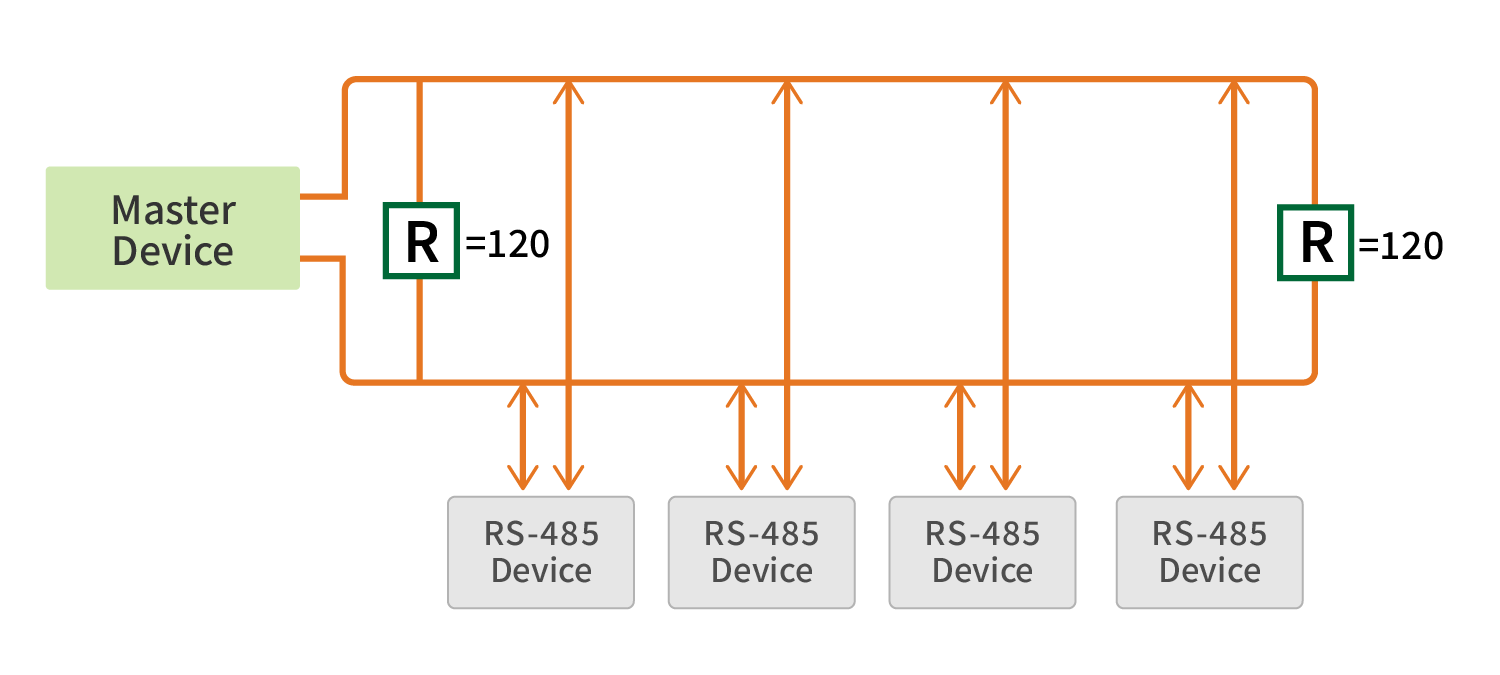
➤ Multi-device networks: In networks with multiple devices, termination resistors help ensure signal stability and reliability.Install termination resistors at both the master and the farthest end of the line. A 120Ω resistor is commonly used, but the actual value should be calculated based on the cable specifications.
4. Two-wire half-duplex
The two-wire half-duplex system enables bidirectional data transmission between two devices, but not simultaneously. For instance, consider devices A and B. During a specific timeframe, data transmission is allowed from A to B, and once completed, data transmission from B to A can take place.
Below is a commonly used circuit diagram for RS-485:
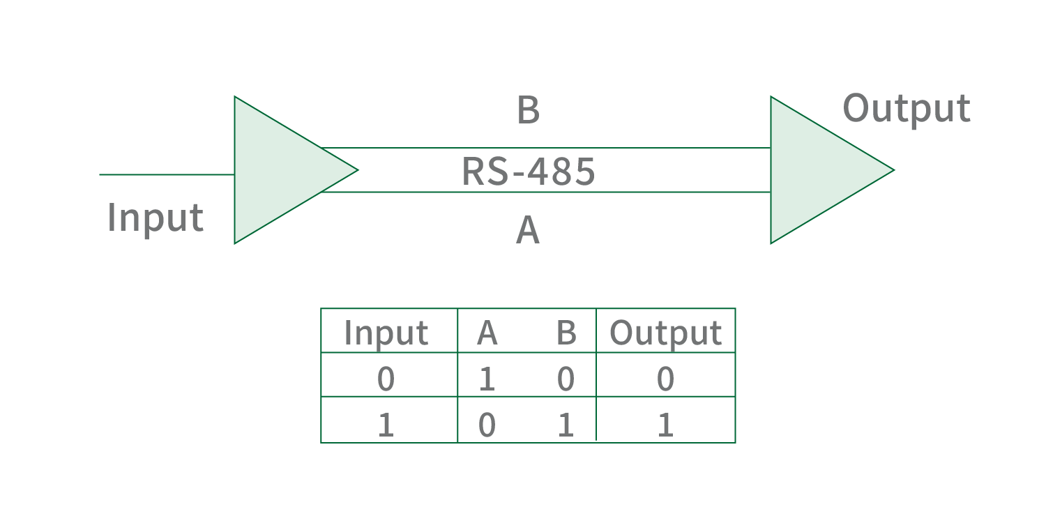
The provided circuit illustrates the fundamental connections for a two-wire wiring setup. In this method, all nodes within the network share the same pair of communication lines. One line, known as the A line (or Data+), is responsible for transmitting differential signals, while the other line, called the B line (or Data-), handles the complementary differential signals. This utilization of a differential signal transmission mode effectively mitigates interference and enhances overall communication reliability.
[2]
5. Suitable Topologies for RS485
RS485 commonly uses daisy-chain and bus (or line) topologies, both ideal for long-distance, multi-device connections while maintaining signal stability. These two are often considered similar in concept.
Network topology defines how nodes like computers and servers connect within a network. Different topologies meet varying needs, impacting performance, reliability, and scalability. Each has specific pros and cons, which will be discussed in relation to RS485 compatibility.
| Name |
Diagram |
Description |
RS485 Compatibility |
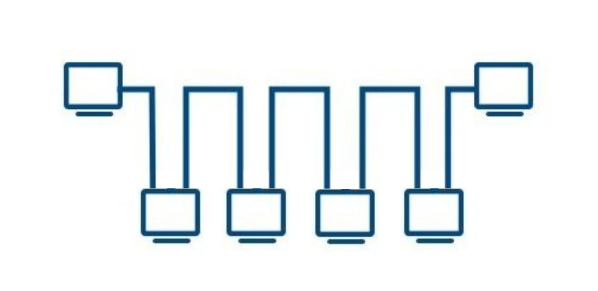
| Daisy Chain Topology |
|
Daisy chain topology connects each node in series, with each node having two connections: one to the previous node and one to the next node. This simple design is cost-effective, easy to wire, and easy to expand, making it suitable for small networks. However, any interruption in the connection can cause the entire network to fail, making it less reliable in larger setups. |
Suitable for RS485, all devices are connected in parallel to a single bus, avoiding long stubs, and using termination resistors at both ends. |
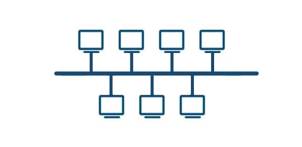
| Bus Topology / Linear Topology |
|
Also known as bus topology, all devices are connected to a central cable called the bus. Any data sent by a device is transmitted along the bus to all other devices, but only the intended recipient receives the message. This topology is easy to install and requires less cable compared to other topologies. However, failure of the main cable can cause the entire network to fail, which makes it suitable only for small or temporary networks. |
Suitable for RS485, devices are connected in sequence without long stubs, thus maintaining signal integrity, and termination resistors can be correctly used. |
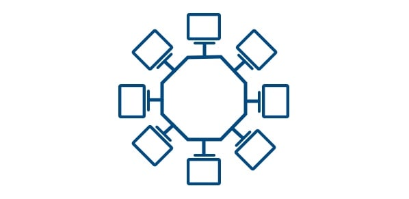
| Backbone with Stubs |

|
A central backbone connects various smaller networks or branches. The backbone provides the main communication path and handles high-capacity or critical traffic, while branches handle local traffic. This design simplifies network management and improves efficiency by centralizing critical paths while distributing local traffic handling. |
Not ideal for RS485, as long stubs can cause signal reflection and affect communication stability. |
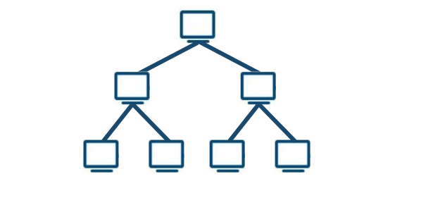
| Tree Topology |
|
A central backbone cable connects different branches, and each branch connects multiple nodes, forming a tree structure. This topology is highly scalable, suitable for large networks that need hierarchical organization. However, if the backbone fails, a large part of the network may be affected. |
Not ideal for RS485, as signal reflection issues arise, especially with multiple nodes and branches. |
| Ring Topology |
|
In a ring topology, nodes are connected in a closed loop, with messages passed from one node to the next in a fixed direction around the ring. |
Not suitable for RS485. RS485 does not support a closed-loop structure, and ring topology can easily cause signal reflection and conflicts. |
| Backbone with Stars/Clusters |
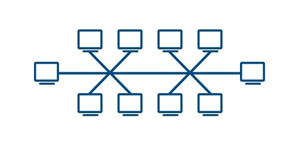
|
A central backbone connects multiple star or cluster networks. Each star network has a central node connecting to peripheral nodes. This design balances load and improves fault tolerance by segmenting the network into manageable clusters while maintaining robust interconnectivity through the backbone. |
Not suitable for RS485. The presence of numerous branches or star layouts can cause severe signal reflection and communication errors. |
| Star Topology |
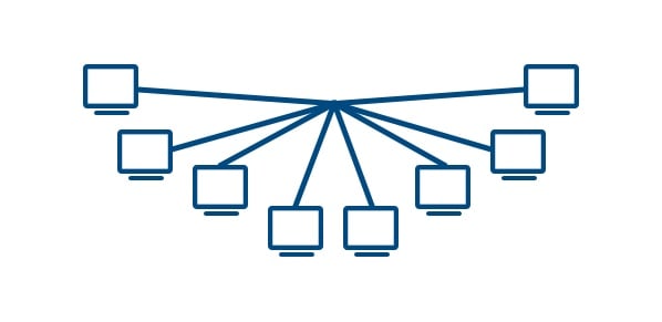
|
In star topology, each node in the network is connected point-to-point to a central node, which then transmits messages to the destination node. The central node handles centralized communication control, which can place a significant load on it compared to other nodes. In a star network, communication between any two nodes must pass through the central node. |
Not suitable for RS485. Star topology can cause each branch to be overly extended, completely disrupting the impedance matching required by RS485. |
The daisy-chain topology is ideal for RS485, minimizing signal integrity issues by connecting devices sequentially. However, longer lines can cause signal distortion, reducing data transmission rates.
6. Communication Protocols for RS485
RS485 is a physical layer communication standard and requires a protocol to manage data exchange and control between devices. Common protocols include:
1. Modbus RTU
Widely used in industrial automation, Modbus RTU employs RS485 for binary data transmission with a master-slave structure. It supports 256-byte data frames and CRC error checking.
2. Profibus DP
Developed by Siemens, Profibus supports up to 12 Mbps, using a multi-master setup for distributed systems and field devices.
3. BACnet MS/TP
Designed for building automation, BACnet MS/TP uses a master-slave/token-passing mechanism, with transmission rates from 9600 bps to 1 Mbps.
4. DNP3
Primarily used in power systems, DNP3 transmits event-driven data with timestamps via RS485, supporting rates up to 9600 bps, commonly in SCADA systems.
5. CANopen
A high-level protocol based on the CAN bus, supporting real-time data exchange with speeds from 10 kbps to 1 Mbps, ideal for embedded control systems.
6. HART
Used in smart instrumentation, HART transmits data overlaid on 4-20mA analog signals, supporting 16-bit bidirectional data exchange for device monitoring and diagnostics.
7. RS485 Case study
Application Example of LORRIC Paddle Wheel Flow Meters in the Central Chemical Dosing and Dispensing System at Hingsen Semiconductor
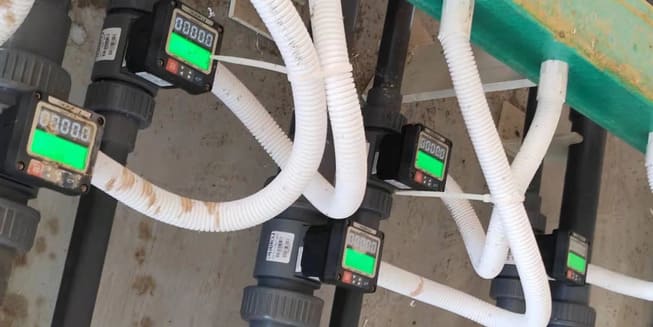
In the central chemical dosing and dispensing system of China's Hingsen Semiconductor, the configuration comprises central chemical storage tanks coupled with dispensing systems at each process point, controlled through valve boxes to regulate the supply of chemical reagents. Each valve box is equipped with a LORRIC paddle wheel flow meter to measure the flow rate of reagents. The flow meters relay flow information in real-time to the central control system via RS-485, halting the supply once the specified amount of reagent is dispensed. Within such a system, RS-485 serves a pivotal role as a bridge, establishing communication of flow information between the central control system and each valve box.